Is there a easy/quick way to align the DXF of a square part, to where it needs to be in sheetcam? I want to make sure the corners of my tubing are lining up.
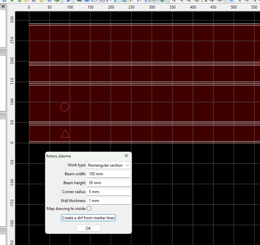
when you use the RotaryPlasma plugin, Options-‘Rotary Plasma’, using ‘Work type’ = ‘Rectangular section’, the rectangle tubing corners are noted with 3 horizontal lines (parallel to X axis) each corner. In the photo, the circle shape is on the A0* face, the triangle is on the A90* face. Y0 is along the A axis, the centerline of rotation.
Once you define the rectangle section (tubing), then click ‘create a dxf from maker lines’. Marker lines = corner lines. Then import the dxf into your CAD program.
Is there an easier way than going back and forth? I’m using SolidWorks. What I am doing is drawing the square tubing with all my holes/angles in it. Then I take and put a .002" slice in the center of 1 flat face so that I can turn it into sheetmetal and unfold it. Once unfolded, save as a DXF and bring into SheetCam.
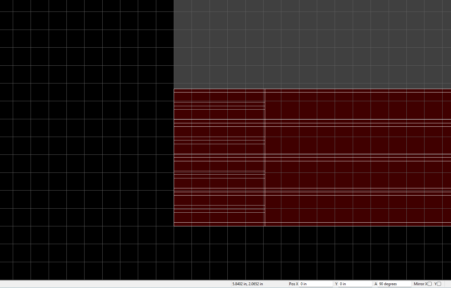
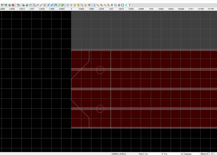
That results in this. Its off essentially 90 degrees. I am able to re-position it so that it comes out correctly, but it would seem that there may be an easier way?
There is no need for “back and forth”. Create the dxf from marker lines one time for each size of tubing (HxW x wall x corner radius) that you will cut. Use the ‘tubing size’ dxf in your CAD as a template for your CAD drawing, putting the marker lines on a separate layer that does not get cut.
Thank you. I have a good grasp on this now.
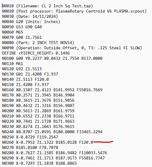
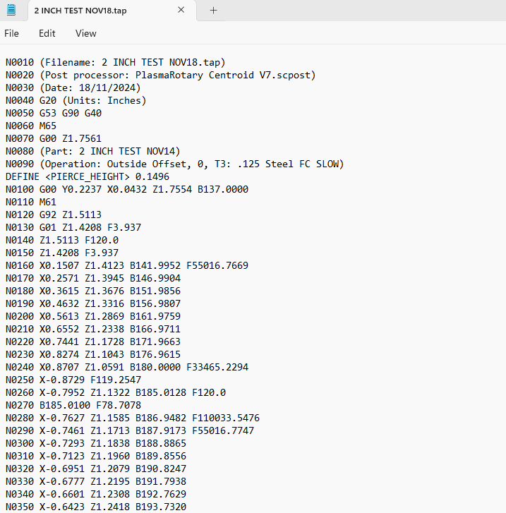
I have another question. When I go to run this job, there is a very slow spot in a rotary move. See attached.
The other lines where the “F” is a very high number work flawlessly. Is this my mistake in something I’m doing or the post? Thanks in advance.
when linear (X,Y, or Z) motion is coordinated with angular (B) motion, the feedrate is relative to the linear axis(es). That accounts for the unusually high feedrates on many linear-angular coordination motion stmts, and since you like that motion when you observer the machine, I’m assuming those are correct.
Those ‘flawless’ motions also have similar distances as line N0260, the one in question with F120.
So agreed, F120 seems grossly wrong in that stmt, and you observe it on the machine as such. F120, more likely purposely, is also used on line N0140, which is purely linear motion, presumable making it correct.
So this may be a bug where the feedrate did not get adjusted for the added angular component of the motion on line N0260.
Please prepare a support.zip file and send to sales@sheetcam.com
Creating a Sheetcam Customer Support file
In the meantime of us looking over your support.zip, I recall sheetcam v7.1.40 having a fix concerning cutting through corners of rectangular tubing, you might give that version a try if not already using it.
This anomaly is also occurring at the very top of the flattened drawing, where that corner is split between the top and bottom of the drawing, just an observation of the transition motion from 180* to 185*.
I am having a hard time finding the version you referenced to give that a try.
sorry about the misleading reference to 7.1.40… in order to get it, you install v7.1.35, take all the defaults during install, and it will eventually ask to auto update to 7.1.40. You will have to reinstall your license file to ver 7.1.35. This ‘Sheetcam TNG Development’ version will be a completely separate install from ‘Sheetcam TNG’ version, so be sure to click the correctly labeled and intended icon on the desktop to open it.
You should avoid double clicking .job files to open them from Windows since there may be some confusion as to which version of sheetcam Windows will launch. Rather, open .job files once you have launched sheetcam as desired from the desktop shortcut icon. File-Open job from the sheetcam menu.
Do I have to do anything with the license like unlicense the current version?
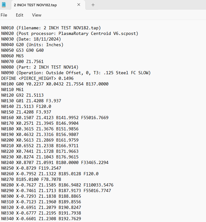
I seem to get the same output when I post.
And with the V7 post as well.
Sorry I think I got the pictures in the wrong order.
no, not as long as your are running both versions on the same computer.
reminder to send us the support.zip file.
Sent. What kind of timeframe/how hard of an adjustment is this to make? Just wondering. Thank you for your time on this.
Diagnostic and fix time is hard to predict. Its in the hands of our senior programmer.
I’ve done some more posting of different things and hand editing the program. It appears to only be an issue from that 180-185 degree area on anything I post. I’m not sure if that helps narrow it down at all or not.
@wags198290 , if you adjust the left side cutoff straight line to (S1) to start 0.020" lower (-Y) from where it is now then you can avoid the erroneous F120 speed in the motion from -180* to -175*. The straight line cutoff starts roughly 0.004" from the top edge of the flattened drawing when in error, and moving just that line south (-Y) to roughly 0.024" from the edge avoids the error.
Still waiting to hear from @Les_Newell on this one.
The problem you describe at line N0260, where F120 is used in a linear-angular coordinated motion, has been fixed in sheetcam. This is not a pp bug but rather a sheetcam rotary toolpath bug, triggered by the start of the cut relative to the flattened tube outline, for instance where it transitions from a flat edge to a corner. See my previous post for a workaround until we can get this fix integrated with others in the next release scheduled in 1Q 2025.
