The doc has been and will continue to be the pp code itself, I did my best to add copious self documenting comments variable names to the code, much to the chagrin of many that read it as I can be very wordy at times
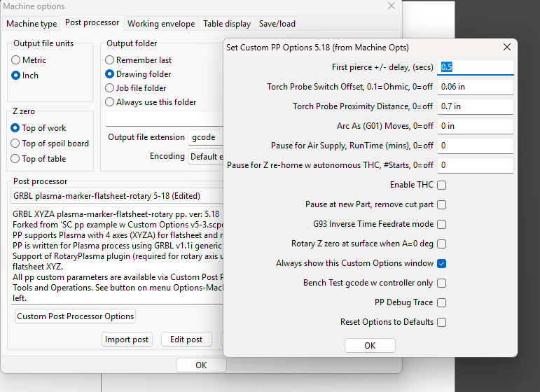
re. “first pierce +/- delay” is a time value in seconds that is added to the tool pierce delay. It’s usually a - value. It is intended to account for the fact that on the first pierce, the cool-down air is not flowing through the torch, thus the solenoid does not have to close in order to reset the blow-back nozzle electrode. This lessens the pierce time, which is going to vary depending on the brand and model of the plasma source. For PrimeWeld latest generation Cut60, this time is -0.07 seconds than normal pierce time. At some point since v5-13 I renamed it “First pierce delay delta +/- secs”.
re. “Torch Probe Proximity Distance, 0=off”, this is a distance value (mm or inch) from the last torch touch-off probe XY position, within which all subsequent start of cut positions will skip a torch touch-off probe cycle until the distance is exceeded, an event which makes the current probed start point the new reference point. Think of it as a radius to a circle in which immediate subsequent start points will not conduct a torch touch-off. It makes for quicker jobs.
That’s a fair question I wear two hats in this forum, my other handle is @sheetcamCS2 , which is sheetcam customer support. Sometime last winter, I had the idea to use my GRBL pp in this thread as the genesis for a sheetcam exemplar pp demonstrating an easy pattern for using custom options, tool options, flat sheet, and conditional (based on plugin enablement) rotary axis function, G93 feedrate option (for rotary), all in one pp. So the separate thread-- Post Processor Example w Custom Options popup window was started. The exemplar quickly became a re-write of the pp I was maintaining in this thread as the GRBL… pp. Honestly, maintaining two versions of similar pps is growing old, so recently I’ve been relying more and more on the exemplar version even for my personal plasma table use. And recently I added a smaller exemplar pp which is without rotary axis function, so it’s easier to read and learn from, as an exemplar should be. That’s why I sent you there. I recommend that you use the exemplar versions, as I suspect they will become the version I maintain most frequently and thus use personally.
Hello BLouChip
I’ve recently changed my electronics board from an ESP32 to a Flexihal GRBL from Expatria technologies Flexi-HAL/README_cdn.md at main · Expatria-Technologies/Flexi-HAL · GitHub.
This board is normally used for driving a vfd spindle for PrintNC. And my plasma table will be dual purposed between a VFD spindle and Plasma torch.
The current settings of the firmware
$30 = 24000 (Maximum spindle speed, RPM)
$31 = 3000 (Minimum spindle speed, RPM)
$32 = 0 (Laser-mode enable, boolean)
If seems that the post processor outputs an M3 command with a value too small
to fire the torch, I can manually fire the torch with M3 S24000 in the console , I did a find M3 S960 and replace with M3 S24000 in my gcode file and the job ran fine.
The values in the PP M3 S960
So my question is do I simply modify the line in the post processor to change it from M3 S960 to M3 S24000
Or I should have 2 settings files for my GRBL settings one for plasma and one for the VFD.
Thanks
You are correct in that you can simply modify the pp to use M03 S24000 in your case for plasma, no need for two config files for your grbl controller. Alternatively, you may be able to use your Spindle Enable output instead of PWM.
warning, TMI follows, but in case you’re curious…
In the latest version of that pp, I’m using the S (PWM) output in what is called an ‘overloaded’ (dual functional) purpose to drive my grbl controller custom build for plasma process. The dual function is:
PWM function: pick the torch trigger relay. Ideally you’d keep the PWM high (100%) to do that, you don’t want the trigger relay to risk chattering. So using S24000 is correct in your case. But the 2nd function is why I don’t use 100% with my controller, but rather the 96% PWM, which is also enough to hold the relay pick due to coil latency. That said, I have added a NE555 timer in the PWM circuit to the relay pick, which keeps the relay activated all the way down to 1% PWM. So the torch remains ON until S=0 or M05, which ever occurs first. I use this signal for torch ON/OFF essentially to enable turning off the torch while in continuous XY motion, usually for the end of the cut. The alternative is synchronous motion, meaning use M05 only, which means XY motion has to complete (to a stop) before M05 is consumed by the controller. The ‘flying’ torch OFF minimizes the kerf save-part divot otherwise occurring when M05 synchronous motion is used. The ‘flying’ torch OFF is applied by a Path Rule such as ‘Before end’, 5mm, “G91 G1X0 S0 \n G90 \n” code snippet. Do this in conjunction with no leadout, and Overcut of 4mm or so.
PWM function 2) manage the Z Anti-Dive circuit thresholds. At 94% PWM, I have a TTL logic circuit with 3 more NE555 timers which blocks STEP signal to the Z motor driver, essentially locking Z when XY is decelerating to negotiate a corner or stopping to reverse direction, while in cutting motion. I could use any S 95%+, but I choose S 96% just to fine tune the % threshold in XY feedrate drop to engage Anti-Dive. And any S % less than 93% will also engage Anti-Dive as long as I don’t Override feedrate at the controller by a % to defeat it. Thus, my THC OFF value for S is 10%, just to keep it far from 94%. And 10% PWM will pick or maintain pick of the trigger relay given the NE555 timer mask on the signal.
All of this MUST be enabled first by:
grbl in Laser mode, $32=1
switching to M04 AFTER the torch is initially fired and Z is lowered to cut height.
the Anti-Dive circuit also has an extra and easy THC enable/disable signal in the way of M7.
See the first post in this thread for a link to the Anti-Dive circuit schematic and some further explanation detail.
04/25- v5.14, clarified ppShowCustomOptions, and changed varDefs table to local var, and machine pause is conditional
05/01- v5.15, merge common improvements from WinCNC pp
05/09- v5.17, replaced nearZ0 with pierceHeight, isolated $HZ from line numbers causing grbl error1
06/04- v5.18, removed OnDrill() logic and custom params for pecking, just use plasma tool def
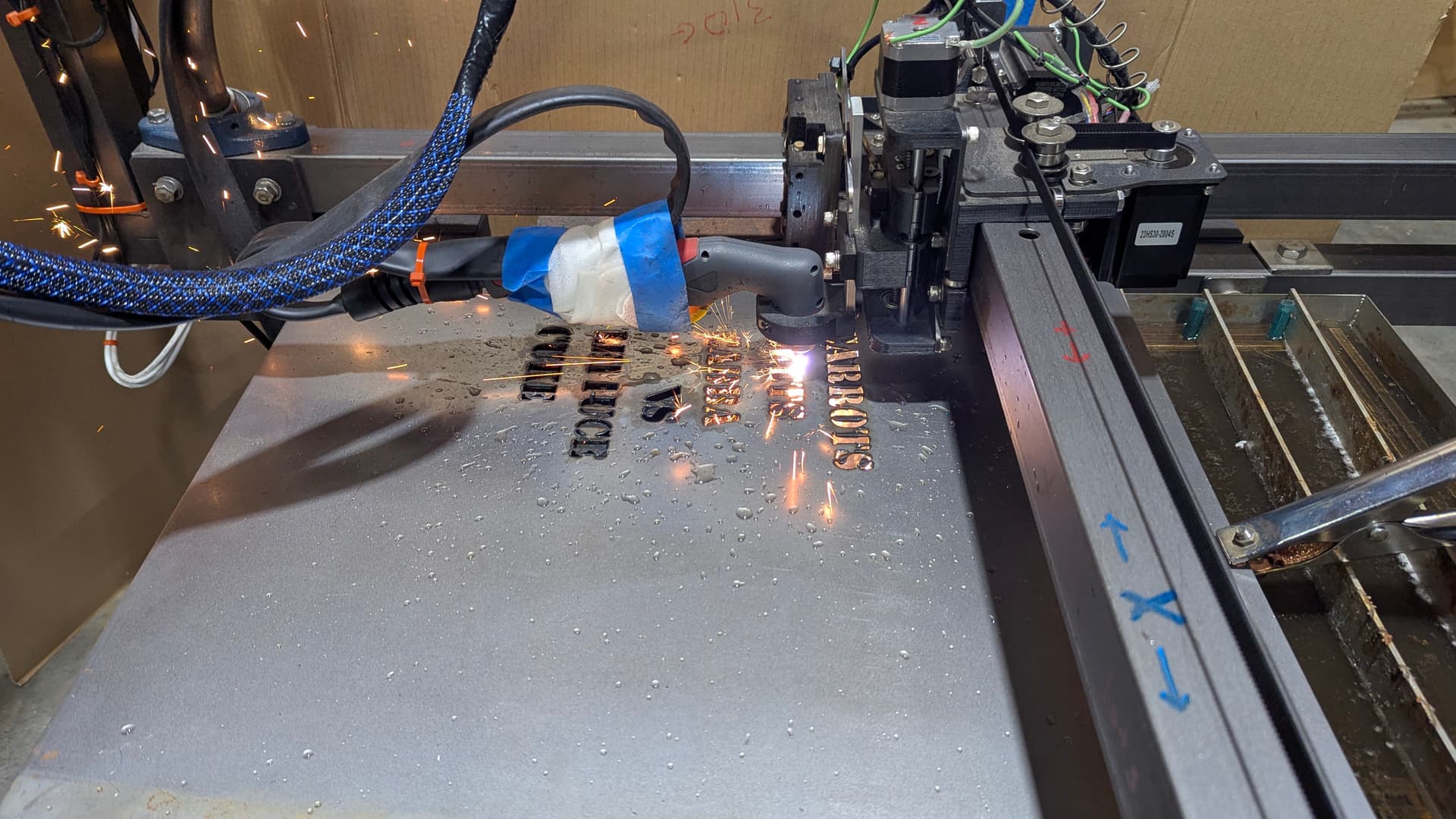
I’ve switched over from using SolidWorks to using Alibre and sheetcam, and it was a little bumpy of a ride, but you made it much easier. Your GRBL plasma-marker-flatsheet-rotary 5-18.scpost was the ticket for my machine, which is JD Garage plasma table with x, y and Z axis’, and a Lotos LTP5500D. I tried a few of your earlier examples and had a few issues, but when I found 5-18, it all came together and I cut a piece for my wife’s she shed, picture attached if the forum will allow a new user. The cut was perfect, right to my machine spec, and almost no dross, which is great for a rusty piece of steel!
Thanks again, if you are in the PNW near Whidbey, I’d buy you a cuppa or a cold beer. And I mean that!