Ok, perfect.
Just reporting another small issue, it looks like letting once the “arc as move” lets it persistent. I mean, if I want to get back to G2/G3 instead of G1, In the settings I put 0 as the value of Arc as move, it will still have the issues I had before. If I just erase the figure,while closing the window it will save a default figure (0.2mm). I guess I can solve the issue by deleting and replacing the postprocessor file, but you might want to no know it and find a smarter way.
It is weekend time anyway, please enjoy!
updated: V30.8
@Tristan86 - I believe all the issues are fixed. Sorry about the problems. Thank you for reporting the issues.
- the TPC (torch probe cycle) you had prior with rotary rectangle tube setup, XA or YA orientation.
- YA and YB orientation and coordinates for rotary rectangle tube, including correct G2/G3.
- ArcAsMoves custom option when set back to 0 (zero).
I used your previously posted .job file as one of several test cases.
I was using sheetcam development V7.1.40.
test G2&G3 on square tube XA.tap (4.8 KB)
test G2&G3 on square tube YA.tap (4.8 KB)
GRBL plasma LDC w Rotary.scpost (53.1 KB)
after some further testing…
update 30.9
- 30.9 simplified logic to adjust pierce delay depending on pierce style
also fixed up some comments and renamed some vars for clearer meaning.
GRBL plasma LDC w Rotary.scpost (53.0 KB)
update: ver 31.0
- 31.0 clarified rotary logic testing in OnInit(); simplified prologue comments
Usage notes made simple-
Import this post processor via menu Options-Machine-‘Post Processor’, click ‘Import post’ button, navigate to downloaded pp, click Open, click OK.
Now go back to menu Options-Machine-‘Post Processor’, see the new button as noted in the screen shot.
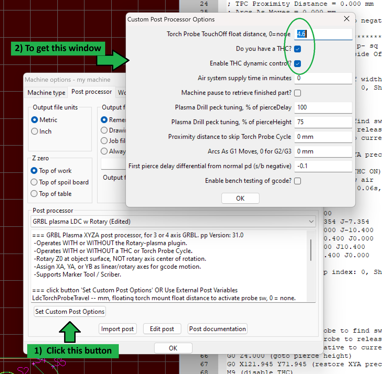
Most just likely need to adjust the top 3 options to match your machine.
If you have a floating torch mount, and if it’s setup with an ohmic probe sensor, then set the Torch Probe TouchOff float distance = 0.05mm or 0.002 in. depending on your sheetcam units as the initial setting, adjust as needed to dial it in.
If you have a probe micro switch on your floating torch mount, then run these commands to determine your floating distance for this pp-
- zero Z (torch tip) on material surface, ensure material does not flex
- G38.2 Z-14.600 F1000 (probe to find sw by closing it)
- G38.5 Z2.000 (reverse probe to open switch)
- G92 Z0 (set temp Z zero)
- jog Z up until the torch tip just clears the material by 0.05mm or 0.002 in. or whatever accuracy you like.
- read your controller Z position and that is your float distance for this post processor. Put that value into the Custom Post Processor Option as shown in the screenshot above.
GRBL plasma LDC w Rotary.scpost (52.5 KB)
It looks like the tool-tube distance would be consistent, just if I actually replace the given values of either A or X with its negative value. Still, my postprocessor is set with A parallel to Y, not to X.
I just tried simulating with the PP set to “A parallel to X”, and the given values were consistent between Y, A and Z, Y values are here spontaneously generated as the negative of X values that were given with the PP set as Y parallel to A.
I may set my firmware driver settings, to reverse A direction so as to avoid tool crashes or excessive distances, but I guess I may have laterally reverted cuts, right ? In that case it is the postprocessor that needs to be addressed, no ?
the maximum vertical radius of a rectangle (approx 1/2 the diagonal) is not necessarily at 45* of rotation, only for the special case of a square is that case true. Also, for a rectangle with radius corners, the exact maximum vertical radius from center of rotation is:
d = var.CornerRadius * 2
MaxRotationRadius = math.sqrt((var.BeamWidth-d)^2 + (var.BeamHeight-d)^2) / 2 + var.CornerRadius
So if you are positioning A axis to 45*, then zeroing Z on the rectangle corner, that is likely not the maximum radius of A axis. Rather, you should hand rotate A until you see the rectangle tube corner roll through the corner apex at the vertical position, hold at max vertical to zero Z there.
re. A axis setup parallel to Y- Bugs were fixed in V30.8. The chuck of A axis is assumed to be at front of machine on XY, and X0Y0 is front right corner, not front left corner. Imagine your drawing in sheetcam as being rotated 90* left. X0Y0 follows the rotation from front left to front right. Be sure to edit the pp prologue for this configuration by setting:
LdcRotaryAxisInit = LdcRotary_YA
Thanks Lou
I was using a square tube, may be I should have explained it.
I am having a very strange behaviour now from the CNC After plunging, each of the lines only referring to XY movements do not actually do XY movements, but have the torch plunging, always farther and farther down. really strange and despairing.
I am not sure whether it is a postprocessor issue, since I see no relation, but I did not have this issue before (or let’s rather say, I had not noticed it, at least) So I wrote an issue on the GrblHAL hub, hoping that would help.
Do you have any idea about that ? I may delete this post here later if I find there is a recognized other cause, but I write here too, in case it may help.
please upload your job here. I’ll be in the shop later today and can test this.
reminder that the Torch Probe Touchoff cycle motion changed back in v30.4, which causes the torch float distance value to change in the pp custom options setup, it will be a smaller value than previous versions.
See this topic and the linked topic it has for explanation.
see also last weeks v31.0 topic as to how to measure torch float distance now.
That is working quite fine for me now. Than you so much for your post-processor !
I still have minor issues, but they are not related to the PP.
(Not relevant to this thread : My 8mm holes are more of an oval shape than a circle, but the oval orientation is not parallel to an axis, so no backlash issues here ; I guess tweaking plunge speed, lead in and lead out may have an effect to investigate. As well, mechanical design to enhance the workflow of WCS tuning, especially A axis, would be relevant since it takes quite a lot of time)
It is really nice to have a working postprocessor combining SheetCAM with Opensource firmware (besides on opensource hardware). That is a very nice and meaningful achievement, I find. Thank you so much.
1 Like
update: v31.4
- 31.2 changed torch fire cmds to use S-PWM signal to pick trigger relay, added OnToolChange().
** This change includes an addition to the bLouChip Z THC Anti-Dive Circuit which allows for ‘overloading’ the S-PWM signal to also serve as the torch ON/OFF signal. This allows for turning OFF the torch while XY remain in continuous motion, making for near divot free shape cuts at the leadin/leadout point. I will post the new circuit schematic soon. - 31.3 - re-ordered some THC/ADC control logic, and improved comments delineating gcode shape cuts to make rare job restarts easier to find.
- 31.4 - made M4 variable S-PWM mode conditional on LdcIsMyCncTable, and Added to M5 block ‘S0’ to ensure turn OFF torch driven by direct connect S-PWM signal.
With grbl in laser mode ($32=1), then using S-PWM signal to directly pick the torch trigger relay, one can use a Path Rule ‘before end’ with Code Snippet
G91 G1 X0 S0
G90
to turn OFF the torch with XY continuous motion (using M3 S960 to pick the relay rather than M4, this can be accomplished without the need for an external electronic circuit). The lead distance before end of cut depends on your plasma source brand and feedrate. At 3000mm/m using PrimeWeld Cut60, I found using a lead of 4mm is about right to minimize the divot otherwise left when torch OFF using M5 only.
GRBL plasma LDC w Rotary.scpost (53.0 KB)
Update and Replacement Post Processor-
I am discontinuing work and maintenance on the previous pps in this thread. I’m switching to use of a new pp forked from this one-
The new pp control logic is easier to read/follow, it provides for easy extensions of new or changed custom options, and it support G93 Inverse Time feedrate mode (most desirable for rotary jobs). Otherwise, it is functionally equivalent to the last version of the previous pp in this thread.
Please advise if you find issues. Thanks.
Lou
begins with “V5.5 test”
GRBL plasma-marker-flatsheet-rotary.scpost (42.3 KB)
“V5.6 test” - compatible with Sheetcam V7.0.21 and V7.1.40 when using ‘Set Variable Operation’ with a boolean variable.
GRBL plasma-marker-flatsheet-rotary.scpost (42.8 KB)
update: V5.9, fixed OnDrill(), via correct currentX and Y when rotaryPlasma plugin is disabled.
GRBL plasma-marker-flatsheet-rotary.scpost (43.2 KB)
update v5.11, fixed to be compatible with v7.0.21 ‘Set PP Variable Operations’.
GRBL plasma-marker-flatsheet-rotary.scpost (44.1 KB)
update v5.13, changed the torch probe distance to be 16mm longer to account for cases when sheet metal warps due to stress relief and/or heat build up.
GRBL plasma-marker-flatsheet-rotary v5-13.scpost (44.3 KB)
Hello Bloupchip I appreciate your releases excellent work as always.
I’ve tested the GRBL plasma-marker-flatsheet-rotary v5-13.scpost on my JDG v2.0 not the XL table and ran into the following minor issues:
1- I don’t have a thc and I didn’t enable it in the popup and this line causes a GRBL error 20 in openbuild v1.0.388 latest M67 E0 Q10 (DTHC OFF)
I simply deleted that line and the job runs without errors
2- the Pierce height and cut height seem to be too high, even if I set them in the tool to 3.8mm piece and 1.5mm cut there are double that on top of the metal part . The only way I can reduce the cut and pierce height is to artificially drop them down to 2.5mm pierce and 0.5mm so 1mm less. This has been a problem with other post processors from @Alsandoval and others
@scoobieguy , thank you for the complement, and glad the pp is working out for you, sort of ![]()
I searched the pp but don’t find “M67”… anything. Is it possible the gcode file was stale and from a different pp?, that looks like it might be from a CandCNC pp.
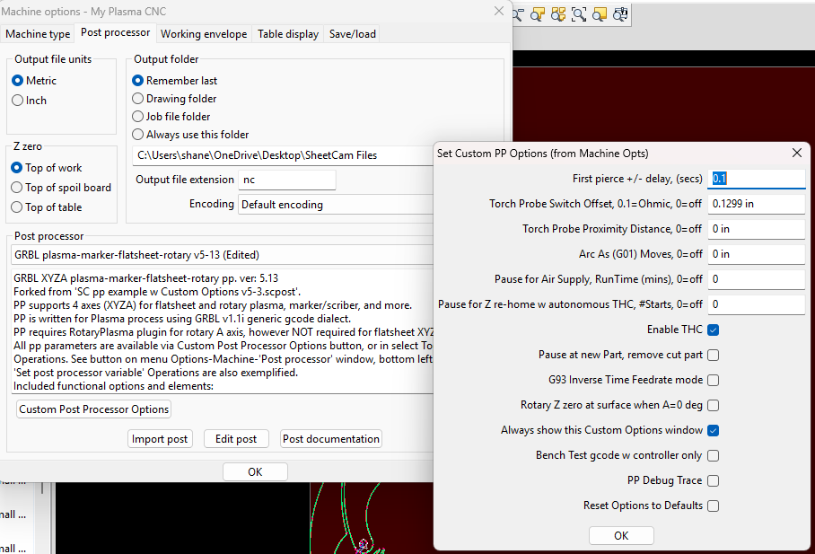
re. pierce and cut heights not right for any pp- that is most likely due to a sheetcam setting; see menu Options-Machine-‘Post Processor’, and the ‘Z zero’ radio buttons. For plasma process, the choice should be ‘Top of work’. The other choices have material thickness and/or ‘height of material above table’ added to the pierce and cut heights.

I think my torch height is getting closer to what I’m setting in the sheetcam GUI thanks for the screenshot. cuts are looking nicer now and I also slowed down the cutting speed.
also I figured out the problem with M67 E0 Q10 (DTHC OFF)
It turned out the be the same issue by another user in this post, I did the same as him import a toolset from another source and it had path rules sets that enable and disabled the THC, as the user said the best thing to do is to build your tool library from scratch.
Works great here for me on a JD V2 table. Thank you:)
1 Like
Hello bLouChip. I have been trying to use SheetCam with my JD’s Garage XL and i keep getting the 20 - Unsupported or invalid g-code command found in block. [ M7 (ADC/THC enabled). I have THC and i have the Enable THC box checked. Any help would be appreciated.
THC setups for something as generic as a grbl controller are going to vary a bit, and some don’t need an enable/disable gcode, Proma SD THC and DANI 7SDP THC are two examples of that. The pp in this thread is written specific to my THC installation and anti-dive circuit, it uses M7 gcode/output to enable the anti-dive (ADC) and in doing so it also enables the THC. Normally an M7 is ‘mist coolant’ output signal from controllers; some grbl firmware are known not to support M7, you may have that case, it seems like your controller is complaining of M7.
You can simply uncheck the custom option ‘Enable THC’ to suppress M7 in the gcode as I recall. If your controll/THC setup must have a THC enable/disable cmd, the pp supports that fucntion and you just need to modify the gcode cmd in the pp that is posted for the condition, the timing/sequencing of posting the cmd may not need change.
Thank you for the information. Ill give it a try.
Hi Lou, Is there any documentation for this PP?
I’m not having luck finding the answers I need.
I guess mostly it’s just 2 things, the “first pierce delay” - is that in addition to the delay in the tool or does that override the tool setting?
And what is “torch probe proximity distance”?