I noticed some of my CNC cuts are coming out with jagged edges. I went into sheetcam and did a close up and found many jagged edges on the file. These jagged edges do not show up on Inkscape. What is going on here? Please help.
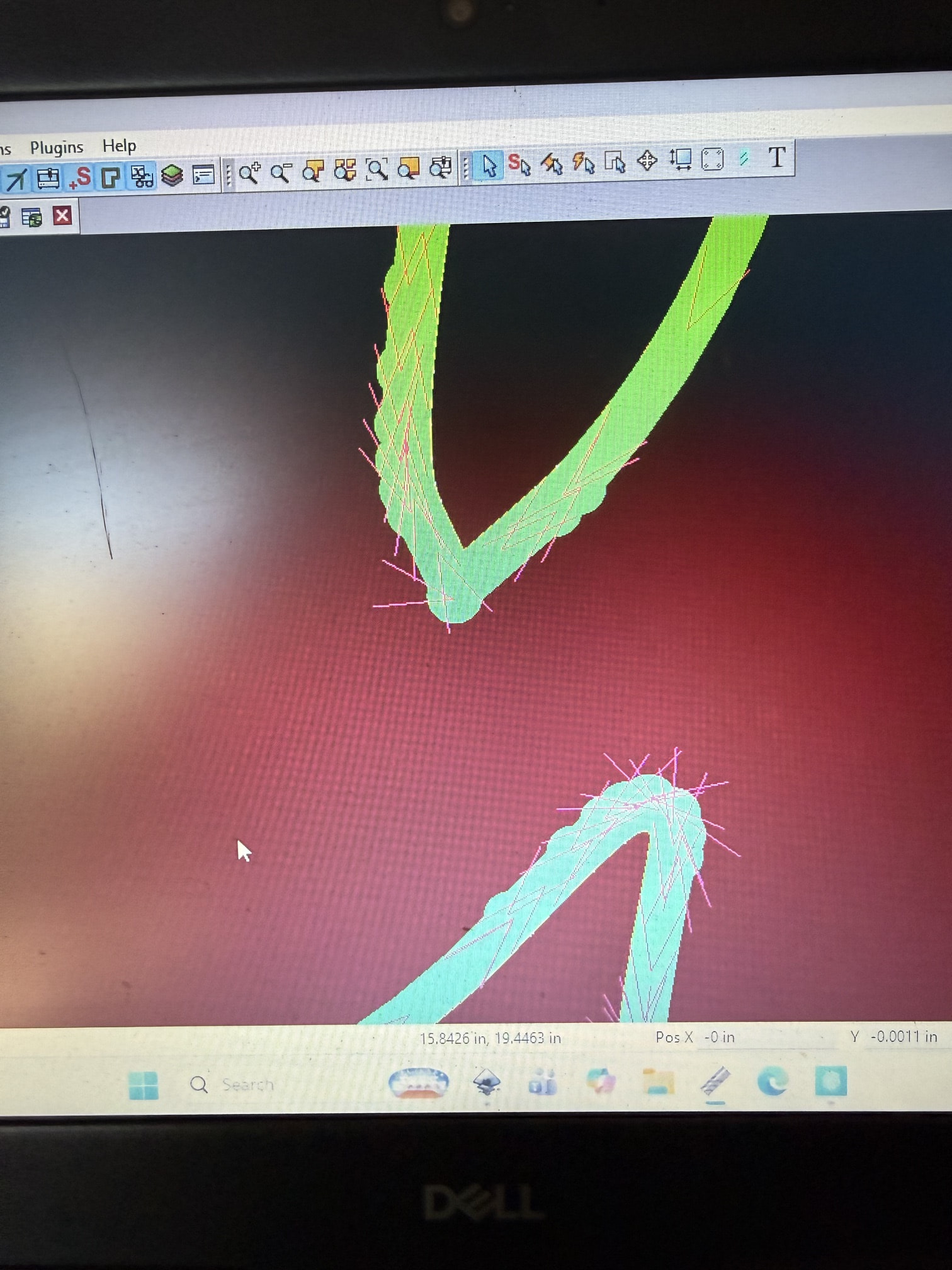
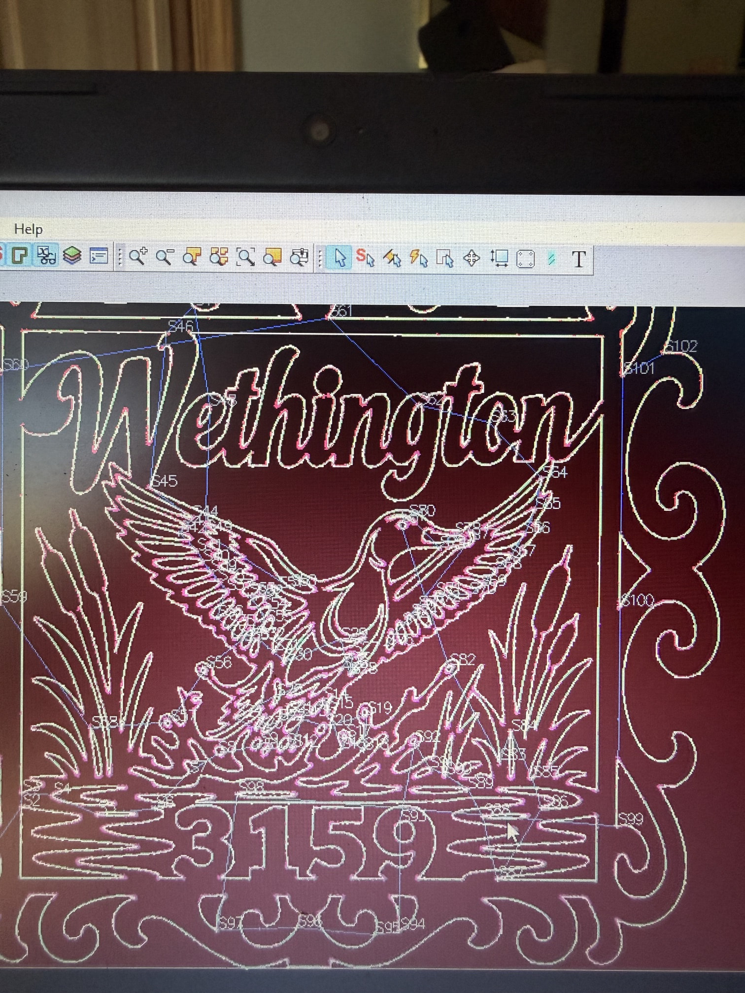
too many nodes or extra unseen lines?
open the file in another program like fusion and see what it looks like. or zoom in really close at that point in the drawing.
The drawing is clear and straight no extra lines nodes do not look over whelming. Just cannot figure this out. Thanks for your suggestions in what to look for.
@donnie , please upload your .job file and .dxf or .svg file.
@donnie , I have not received your files.
A point of use for this forum… There is no need to keep opening new topics in this forum each time you respond on the specific problem you describe in THIS topic.
Second, the process to UPLOAD your files to this forum involves a simple REPLY to this posting.
In the Reply message box, simply click the Upload icon as noted in the following photo…

Then click the blue Reply button and its uploaded here for anyone to review and help. I will be glad to review it when you upload as noted.
Inscape is natively vector based sheet cam will take the SVG vector based image if you convert to DXF and export that the DXF will have lots of little jaggies in it because it will be converted to very small line segments
I have done this hundreds of times, why all of a sudden am I getting the jaggies. I have never had this issue until about a week or two ago? So what do I need to do to correct this?
@donnie , without seeing your .job and .svg or .dxf files to diagnose the problem with certainty, I can only speculate on what is causing ‘the jaggies’ as seen in your first screenshot of the toolpath. It appears, from the toolpath cut direction arrows, that you have more than one contour line traced on the shapes, at least the shape segment that you’re zoomed into. This can occur when CAD (inkScape in your case) ‘traces’ a graphic image that is low resolution (pixelated). When that occurs, you should clean up the duplicate/multiple trace lines in CAD before you save the .svg or .dxf file for later import into sheetcam.
Depending on your sheetcam settings (Options / ‘Application options’ / ‘Drawing import’), sheetcam will attempt to cleanup duplicate lines also before calculating or determining the toolpath. It’s not 100% fool proof, and highly dependent on the proximity of the duplicate lines to each other. If lines cross each other, sheetcam will segment the shape into numerous open and closed contours. Thus ‘the jaggies’ may be pierce points and/or lead-ins.
Lastly, both inkScape and sheetcam retain option choices (from last used state) in all of their UI dialogues. Thus, if you purposely or inadvertently changed a UI dialogue option choice at anytime, the state of that choice is retained until you change it again. That’s done for convenience but it makes for strange results such as what you are getting when the change was inadvertent / unknowing.
Again, if you post / upload those files I’ve been asking for, I can review them and perhaps we’ll know for sure why you have ‘the jaggies’.
simple question are you using DXF or SVG if you are using DXF try SVG and see if your results change
I recently learned that DXF is not a vector format DWG is so exporting SVGs to DXF can result in unexpected abrupt and frequent changes in direction since sheetcam can accept the vector format I would use that and make sure that your file is single layer or that at a minimum you are asking seetcam to operate on the correct layer
Thank you for all of your help and expertise in this. You have been truly helpful.
share what you learned so others can benefit
There are people on here that are extremely knowledgeable. They can certainly help you and you can learn much. Just be respectable and share anything you can as well as gain knowledge. Welcome to the community.