I’m making a post processor for a 1997 CNC plasma machine (Oxyser) with a control called Power C (EIA Gcode), but I’m having problems when the machine tries to make arcs.
With the circles I have activated ARC_SEGMENTS in the post processor options, but when the machine is cutting it only cuts half of the circle and then the head rises, and the G code doesn’t look bad, M7 then 4 arcs and M8.
But when you run the program on the machine only the first two arcs are cut, then the head rises and continues making what was missing from the circle but without cutting.
Hope someone can help me, thank you very much
The easiest way to assist is to examine the job, post processor, and gcode files
Please upload your .job , .scpost , and .tap files.
Hello,
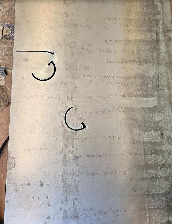
I’m attaching the files, as well as an image of the test performed on a sheet metal. As I mentioned, it only cuts half of the circles even though it completes the entire path. The outer contour also has problems when it encounters an arc.
I’m also attaching a program for that design that works correctly because it was created with the original software.
Is it possible to have Sheetcam also generate G41 and G40 codes?
Thank you very much for your help! Have a nice day 
Oxyser Postprocesador Forum.scpost (1.9 KB)
testProMotionNestRobotronicOyTXT.txt (847 Bytes)
testPostprocesadorForum2.txt (1.2 KB)
sanchezNacho.job (5.9 KB)
Its going to be a few days or so before I can study this thoroughly, but if someone else on the forum would like to do so, that would be helpful.
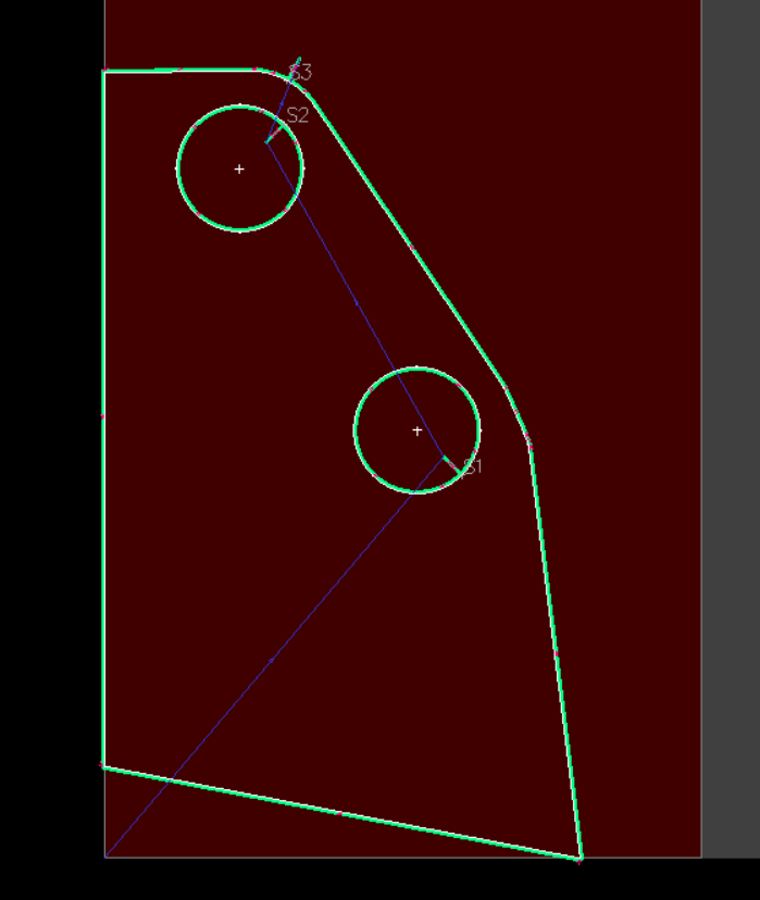
The gcode does not import into sheetcam with the same drawing as you have in your job file. Yes, gcode can be imported to reverse engineer the drawing. Its also a means of validating the gcode, as is the case I’m using it for.
#2- I see G36 and G38 codes in your gcode file. Please provide definitions for them, or even better, upload the gcode programming doc for your controller.
G38 looks like some sort of circle or arc command given it has I and R words. That could be in conflict to the G2/G3 blocks.
#3- As a quick fix perhaps, you can use sheetcams ArcAsMoves() function to have all arcs replaced with G1 blocks.
Hi,
I found the problem.
In G38, I was writing a 0 instead of an O at the end of the command…
G38I2R0.2J40O2
I don’t know what that command is used for. I don’t have the documentation for the control, but it works fine now
But I need to fix the tool compensation. How can I get SheetCam to generate G41, G42, and G40?
Thank you very much for your help.
Sheetcam is best used without cutter compensation since since sheetcam factors the kerf width into the toolpath. Just use G40 cmd in the gcode prologue and you are set to go.
Can the actual direction of the cut be accessed from the postprocessor code?
And I would also like to ask if it is possible to edit only a specific entry, for example a 10mm tangent when all the others are 15mm.
Thank you very much
There are three undocumented pp functions to assist with cutter compensation, see below. Sheetcam does not advocate the use of these functions as it can lead to a cascade of toolpath issues, so use at your own risk and with support limited to this disclosure of experimental existence for your trial and error.
We suggest that you limit compensation offsets of no more than 10% of the tool diameter to maintain toolpath integrity and co-mingling with uncompensated toolpaths.
function OnOffsetNone()
         post.Text(" G40 \n")
end
function OnOffsetLeft()
      post.Text(" G41 \n")
end
function OnOffsetRight()
      post.Text(" G42 \n")
end
re. leadin length editing- not advised to do this. A better solution is to move the contours needing a different leadin to a separate layer, then define a specific Operation with adjusted leadin for that layer.