29.4 corrected datatype on LdcPdNPFADelta custom option
29.6 per Les, moved conditional load of rotaryhelper to OnFileOpen()
30.1 correction to conditional load of rotaryhelper
30.2 fix to OnArc() YA, YB logic: swapping IJ to stay in sync with XY
update: v30.5
30.4 added reverse torch probe to release material flex; and added LdcAirSupplyTime = 0 has off effect
30.5 added LdcZ_ReHome as job shape count before rehoming Z to eliminate THC induced Z error
Thanks for asking, but this is not an ohmic sensor circuit. This is a Z anti-dive circuit when the THC correctly senses a spike in arc voltage, but at a time when the voltage spike is not caused by incorrect torch height, but rather caused by an automatic controller driven reduction in feedrate due to XY motion either starting, stopping, or cornering. Such a circuit, external from the controller, is useful when the THC is designed to operate autonomously from the CNC controller, such as the case of my Proma THC SD brand/model, and clones that are like it. The circuit will prolong the continuous CNC plasma cutting time by better keeping the Z axis calibrated to its machine zero point. An autonomous THC manages Z motion to maintain the arc cutting gap without feedback to the controller, thus it will leave Z position different than where the controller last positioned it, thus out of calibration. If this occurs consistently in the same direction (up or down) on every shape cut in a job (continuous cutting), even to the amount of 0.1mm per cut, then after 10 shape cuts Z is out of calibration by 1mm, 100 cuts = 10mm, and so on until Z is re-homed to calibrate its position. This out of calibration growth can cause Z to either physically overrun its axis limits when moved after the job completes, or cause the controller to throw an axis limit error during the job if the controller runs with Soft Limts ON.
I have a weird issue, And I think it is related with the post processor
I just bought this morning the general SheetCAM license and its rotary plasma plugin. I designed a piece and prepared its cut, but the Gcode was irrelevant at least with Probe Cycle. I had the line
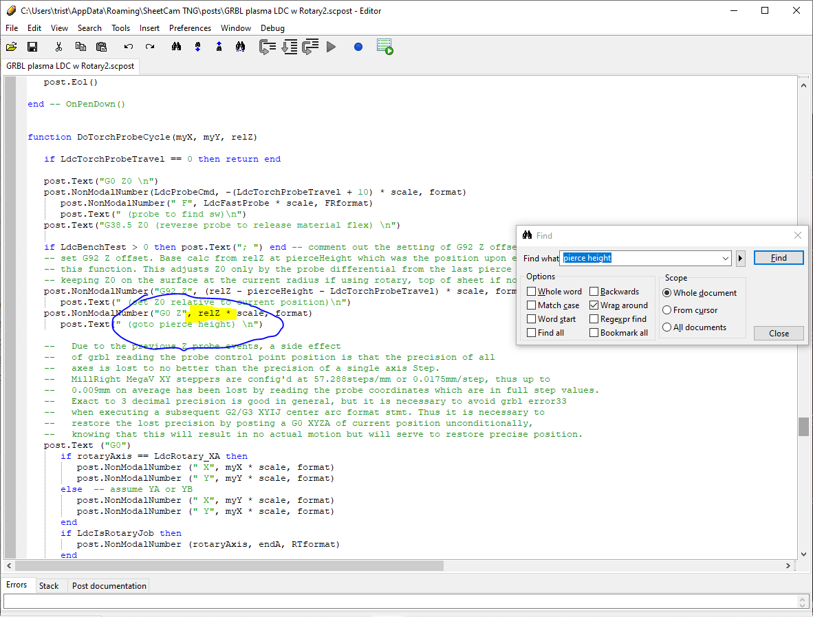
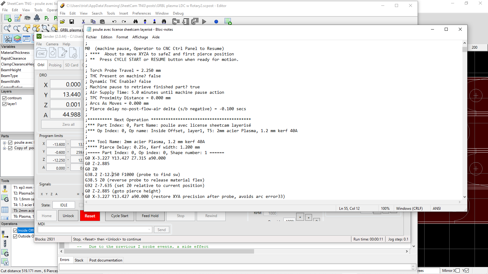
G92 Z-7.635 (set Z0 relative to current position) ;
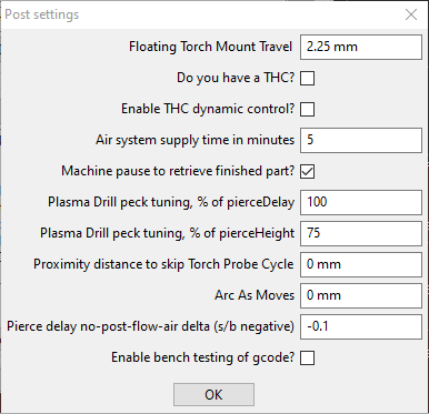
instead of 2.25 as I set for my floating torch mount travel. And then the torch goes down again !
G0 Z-2.885 (goto pierce height)
Even though my pierce height is set as 2.5mm.
(Then I noticed the holes I wanted to make are cut a little bit more than twice each ; could it be from a vectorial double drawing mistake ??)
The last days I had only the evaluation license, no plugin, but cutting each face separately was fine. I just had handwritten “G0 Z up” then “G0 A something” for each face, and was OK. The only other change I remember was to have rotary axis set as parallel to Y instead of X, (thanks for having addressed this issue too, bLou) Of course this change is not related
It is frustrating as I was expecting at last to have a tool to cut tube edges too. Hopefully you have an idea of what may cause that, thanks in advance for any clue
You must be cutting a ‘Rectangle tube’ on rotary, is that right ?
Please upload your gcode file and .job file. I’ll have a look.
what version of sheetcam are you ? Help-About.
Yes, it is a square tube. The Square corner radius is wrong , like one mm undersized, but that should not have these consequences I guess.
My Sheetcam version is 7.0.21 poulie avec license sheetcam layerisé.job (25.7 KB)
The Gcode can not be generated under a format the forum accepts to import. You can find it here
I just mad another test, with a round pipe. I have no issue with Z height in that case, the probe offset is correct and the pierce height is fine too. However a very strange inconsistency occurs. In my PP settings, my proximity distance to skip torch probe cycle is set to 0. But the second cut of this job skips the Torch Probe Cycle. And then, the other cuts of the job have the TPC implemented. It is only this 2nd cut which has its TPC skipped. This gcode is here
[test on round tube.job|attachment]
The job is this one (upload://3kAl4a7LGjx9CfVMz6cD3tB36of.job) (9.5 KB)
Have you ever found a big bend in a tube, round or square, where the Z probe is necessary after one first TPC, because of thermal distortion or whatever else ? If you want to improve the postprocessor I am happy to help providing these feedbacks. As for now I am thinking TPC is not as important in most tube cut routines as in sheets cutting. May be that would be different for people who want very intricate and long longitudinal cuts, with therefore much more heat and less tube profile holding itself consistent as a whole.
Your postprocessor is really nice anyway.
For the next few days I have the feeling having for each job one first hand-corrected probe routine and skip all the next ones will be enough. I can still do other tests if you wish anyway.
OK, I just read again the gcode and it looks like I just did not understand your scope. I expected Z to be zeroed for each face of the tube. I had not expected that you would keep a single Z reference even through various probes cycles on each face. Something went wrong on my test, and at first glance I saw these weird negative Z values and thought it was the cause of my issue, but I was probably wrong in my interpretation. I hope you have not lost time yet with my alert since it may be false. I have to take more time to see what went wrong with my job (the TPC skip inconsistency remains valid though)
@Tristan86 - Correct, Z is zeroed by operator once before the job. Also- Use of my pp requires Z to be zeroed on the cylinder (or virtual cylinder) surface, unlike other sheetcam pps where Z is zeroed at rotary center of rotation. For rectangular tubing and I-Beam, the virtual cylinder is the diagonal, thus Z should be zeroed on the apex of any corner. I tried to ensure good comments in the gcode to advise of this, let me know if comments could be improved.
So when cutting rectangle tubing and I-beams, Z will show negative values on controller DROs usually while cutting, since it is rarely at zero.
re. proximity distance of 0 causing second torch touchoff probe cycle to be skipped- that was bug in my pp when cutting rotary. Its fixed in the attached pp version. Thanks for reporting the bug.
I am surprised to see so many views for this thread, it really looks like a lot compared to some others. Could there be some bots here ?
I just come back to my tests, but have a new question. I see through SheetCAM square tube do start at the apex. So considering you implement both a lead-in and an offset, the position of the torch is quite far (I mean on XY plan) from the midle of the edge. The torch is therefore not perpandicular to the tangent of the edge arc. It worries me, as the Z probe routine may be affected, the torch sliding on a steepy slope and going not so right along Z axis first instead of quickly activating the probe swicth.(my CNC may not be rigid and stiff enough) The accuracy of the probe cycle may be affected. Have you been exposed to this issue ? I am considering to erase probe cycles from my Gcode for each start on the edges. (Unless there is a way to have the cuts not starting close to the edge and have the probe made where the rotary axe DRO is close to 0°, 90° or whatever multiple of it ?)
I have the feeling it was a cause of my last failure. I will try adding a lots of M0 pauses to measure and investigate that.
@Tristan86 - a couple of points to note that will improve your rectangle tube cutting.
sheetcam allows you to place the start (pierce) point of a shape cut anywhere on the shape that you desire, and you can position it to account for the leadin also.
Its not likely that you need THC active or torch touchoff cycles for rotary cutting, so you can disable those features with custom options settings in the pp. THCPresent uncheck the box, and to disable all but the first torch touchoff probe cycle use the ProximityDistance value, use a value 2x the length of your tubing.
sheetcam uses coordinated XYZ motion when cutting the corners of rect. tubing and I-Beam. The reason is to keep the torch inline with the radius of the corner, keeping the cut edge square to the surface. You can use rotary simulator in sheetcam to see this motion very clearly, it is intentional. Round pipe does not need coordinated XY motion as there are no corners, the torch is always inline with the radius of the surface.
One more note- recently sheetcam fixed a rotary rectangle motion bug concerning the motion around corners. You may be hitting the bug. It’s fixed in the development version 7.1.40. You should try that version to be sure.
[Erratum re-edit about last paragraph: I was not precise with G2/G3 issues coming from the postprocessor symptoms. I just made a few tests if this was due to my CAD making overlays lines or other things. My CAD does not look guilty, since I had issues with both inkscape and SheetCAM generated circles or arcs. The issue did not appear with flat sheet or round tube profiles, only with rectangular profile tube cuts.]
Thanks.
It looks like you confirm the way I would be taking, just one first probe for tubes. I guess just putting a big figure to the PP setting “proximity distance to keep Torch Probe Cycle” will avoid unnecessary issues, and have the cut be quicker.
Regarding the first topic, I am not sure it is possible to choose the start point of a contour cut the case with rectangular tubes (but I have not tried the development version yet). This is, I assume, because the software identifies the tube as a sheet on which it is asked to cut starting form edges. The software only allows to cut starting from one stock"edge" or the other, depending whether we want in or outward offset. At least I was not able to choose another startpoint for this case. Never-mind, without probes need, there is no big issue any longer, here.
I am far away from my CNC this week, and could no try much to tune or use it. However there is one trouble I saw last week, that is worth mentioning. On circle cuts, the postprocessor makes the torch turn around three successive circles. I can see the issue comes from the postprocessor since the SheetCAM simulator only makes one turn, and Gcode simulator confirmed me I had no hallucination.
One last but telling test. Considering this I-and-J-reversed hypothesis (gcode made three successive arcs, each long as 3/4th of a round perimeter, with either I or J =0), I switched back the postprocessor to A axis parallel to X,it was previously set as parallel to Y. And once I had this "rotaryAxis = LdcRotary_XA"setting , the gcode was just perfect.
I then tryed to change the Gcode to see how things were reversed.
As for what I see with the gcode in the “correct way”:
Each circular “final piece edge cut” is made of various g2 or g3 movement. They are composed of a first smaller G2/G3movement, to reach a “I/J” symetry coordinate. Then arcs of the same length are done, where I and J values just flip around that symetry, until it is time to have a last “going out movement” to the last part of the cut. If one wants to make a full circle, it is quite simple, one first movement is done, then 3 times a 90 degrees arc, then a last one to complete 90 degrees together with the first one.
The issue with postprocessor set as rotaryAxis= YA, is that the cuts follow the same pattern, on the contour line, except each 90° arc is actually 270°.
It is possible to solve the issue by cutting and pasting backward the X and Y coordinates of each G2/G3 lines (and tweaking the I and J offset)
But things get then more complex : When cutting less than 360 degrees, as well when having a chord joining the arc ends or correcting the sharp ends contournings to offsett the kerf width, the gcode edition starts to be very messy. I started manually to figure out the issue, but with a very myopic scope focussing on gcode editing, not general geometry axis swich. I guess a proper postprocessing correction would be much more relevant to avoid this tedious intents.
Meanwhile I may just toggle my Y and X drivers and limits wirings from the controller.
I’m confirming a bug in the post processor as you described.
I’m continuing to study it for a fix.
For the time being, a workaround should be to use ArcAsMoves custom option in the pp.
I am sorry to inform the “Arc as moves” setting does not works either with square tubes. My tests showed me that :
-Arcasmoves do not work with square tubes, whatever the rotary axis orientation settings ; it reacts giving plenty of movements including A and Z, in spite of working on the centre of one single face, not touching the edges radii
-it works fine with round tubes and “rotary flat sheet”.
-the resolution of arc as moves on round tubes has no obvious meaning (switching from 0.1 to 0.02mm, the number of gcode lines for one same single circle increased form 27 lines to only 64 ; surely not a critical issue)
I am happy to report bugs or things I do not understand. However your postprocessor works fine in most cases. inverting my X and Y wirings may be my fine solution to that issue.