is that the translation that is included in the official package? If yes, I would like to correct it. Beside some spelling errors there is also a functional wrong translation…
You can edit the translations. Install the development version of SheetCam then take a look here https://www.sheetcam.com/language for instructions on how to edit a translation. I would welcome any corrections to the translations.
The Linux version is currently a development version that is a few releases behind the Windows development versions.
If you want the latest dev you can run the Windows version using Wine. Most distributions include Wine.
Hmm why is the development version required? The language files are still included in every TNG version I have installed.
But your tutorial with poedit don’t work so. I had to convert the *.mo-files to *.po-files to be able to edit them with poedit.
For other users simply run
“Peripheral feed rate” is a path rule. I haven’t tested and I can’t find it in documentation. But I think it applies to outer and inner radius so that the feed is constant on the parts edges instead of at the center of the tool.
In which context is “Peripheral feed rate” appearing?
This is a rule for milling/routing. When cutting a stright line the feed the cutter sees and the machine speed are the same. However when machining small holes the outside of the cutter is moving faster relative to the work than the commanded speed. Applying this rule adjusts the feed rate to compensate.
&Add breakpoint
This is in the post processor editor. You can mark break points in the code. When the code is running and hits a break point it stops so you can look at the variables. This is very useful for debugging.
Acceleration distance
This is used in the laser plugin. It is the distance it takes the laser to accelerate up to cutting speed.
Okay nice, thanks.
But a lot of work. There are so many errors in this translation I never would have expected.
It seems that this translation is not based on the translation of the earlier non-TNG version. Isn’t it? That version was better I think.
While translating I discover sometimes new functions.
In menu “Operation → Operation table” there are tabs for Contour, Pocket, Spiral pocket and so on. But every tab shows my spiral pocket. Should that be so? If yes, I haven’t understood the function of this window…
Hmm yes then we have to edit all other translations. I think that’s not worth it.
Ok then the tool would have the name of the operation. The user would understand that though.
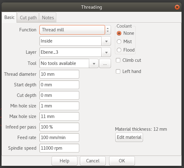
In the dialog ‘New thread mill’ the parameter ‘Thread depth’ - is this the maximum depth that the mill is able to mill?
(This parameter is not described in the manual)
And something about thread milling I wondered.
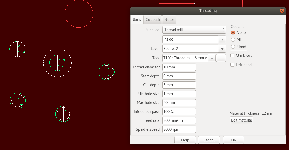
Why is the thread diameter determined by the tool and not by the drawing hole size?
I think thread milling is comparable to pocket operation where pocket size is determined by the drawing. The thread mill is capable of milling different thread sizes, so if I want to do that I have to define multiple tools for the same tool…
The circle is the drill size. The outside diameter of the thread would be the hole size plus twice the thread depth.
The diameter in the tool definition is the diameter of the thread mill, not the diameter of the finished thread. This must be less than the drill size.
‘Cannot cut on the edge of a flange’
This is used by the rotary plugin when cutting I beams. The flange of an I beam is the top or bottom.