I have just built my first plasma CNC machine and got it running in the XY and Z axis. The Z axis has a floating head, but I have no idea how to set it up. The system uses GRBL 1.1h and a Nano Arduino for the control. UGCS to send the gcode.
I have homing on all the X Yand Z, all working correctly. The Z also has an extra probe switch that is wired up to A5.
I have loaded a modified version of GRBL post processor that uses M4 and M5 to turn the plasma on and off. The description of the original post processor says that it is for THC and also without THC (I will get one of those at a later date that uses step dir signals)
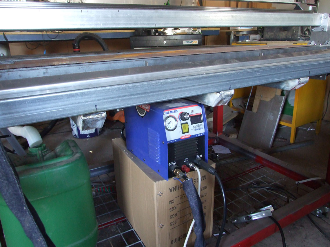
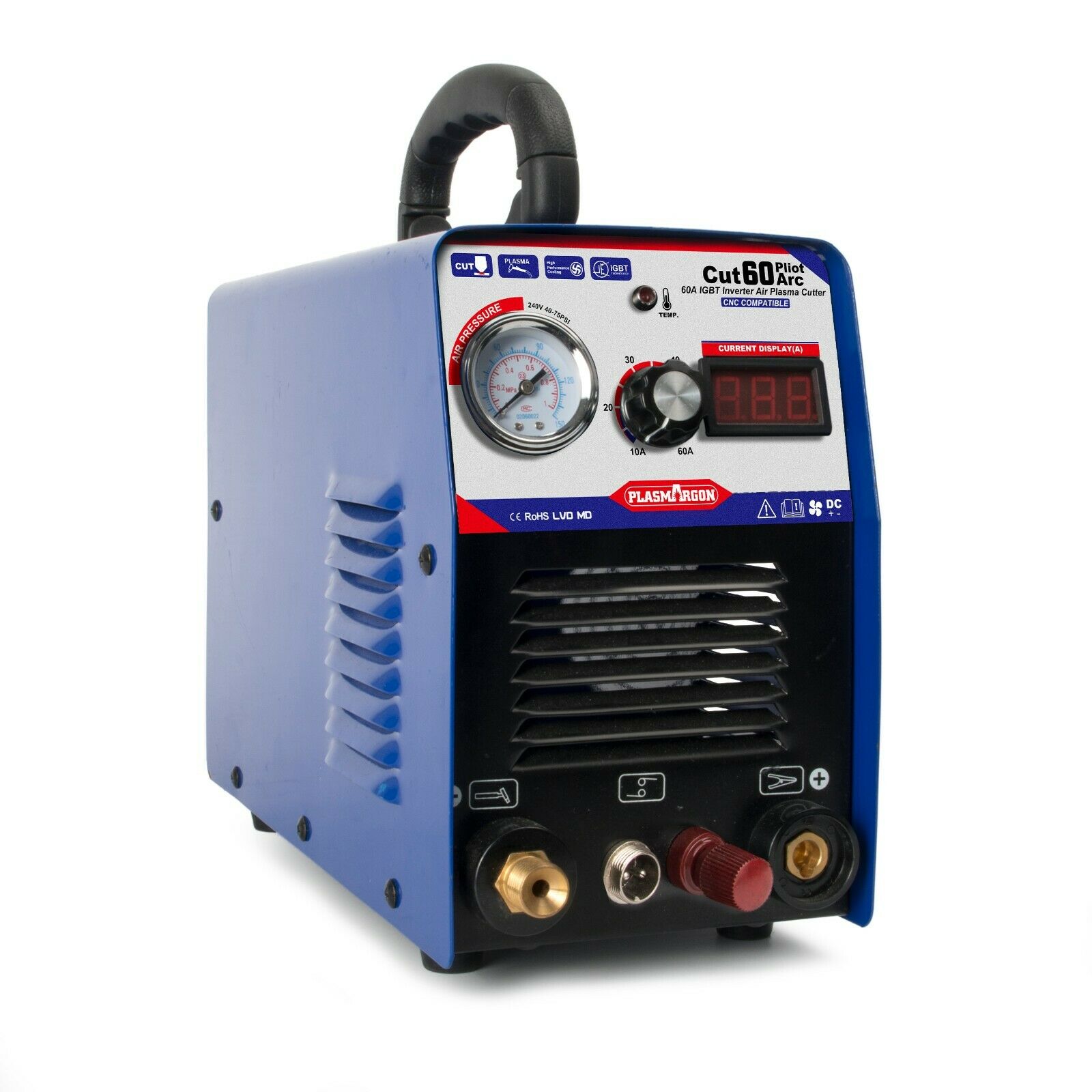
The plasma cutter is a Chinese CUT50 with pilot arc, no information came with the machine, no settings or recommendations of how to use it.
My questions are, how do I setup the floating head switch? What are some ball park cutting speeds for the plasma cutting 3mm mild steel? I have no idea what the nerf cut should be set to.
What is the process for making my first cut? Do I manually zero the Z axis and let the Sheetcam file take over?
I will probably have many more questions as I learn my way with this new adventure I have embarked on.
OK, it looks like I may be too vague for anyone to be able to help, so I will make a few stabs in the dark and hope I don’t break anything.
I am sorry for my vagueness, but all this is new to me and I really don’t know what I am doing yet, but I will learn (one way or another)
I guess the first thing I should try is to determine the speeds needed and also the nerf setting in sheetcam.
I will draw a square 50x50mm and set no nerf size and see what I cut. By doing that I hope to be able to find out what the actual size is of the square and that should determine the nerf size for future cuts.
I am not sure about the speed setting, but using say 25 amps and a speed of 2000mm/min (about 78in/min) I will give that a try and see if it is too fast or too slow.
As I don’t know how speedcam works with the PP that I am using, from a unpowered test it seems to not do any probing, so I will lower the nozzle down to the surface and reset to zero. I see in the PP that the nozzle is then lifted to 1.5mm while cutting.
All a bit hit and miss, but the only option I have so far.
I know nothing about the equipment you are using, but can offer a few suggestions.
First off, the kerf width is how wide the cut is. Generally the thicker the metal, the wider the Kerf. So the Kerf width will vary for each different thickness of metal. The cut speed and cut voltage will also vary with each thickness of metal. Which means you will need to build a tool table for all the different metal thicknesses that you will be cutting.
To give you some ideas, you could go to the Hypertherm website and down load a user manual for one of their plasma cutters. Since you have no documentation for your plasma cutter, you will have to determine pierce height, cut height, cut speed, cut voltage, etc. by making many test cuts to see what works best for your equipment. I’d probably start off with Hypertherms settings and go from there. All of these settings depend on each other, so changing one setting will affect other settings.
To get started, choose a pierce height and cut height. Turn off any Digital Torch Height Control you may have. Cut a straight line, paying attention to your actual cut voltage. That voltage will become you set cut voltage in your tool table for the cut height and cut speed you have chosen. Cut speed will depend on how the cut looks, how much dross is produced, how hard it is to clean off, etc. The cut height will depend on how square the cut is. If it is wider at the top than the bottom, lower the torch. If it is wider at the bottom than the top, raise the torch. When the torch height is just right, the cut will be fairly square.
Hopefully these tips will help you get started, Steve
The voltage is read between the work clamp (+) and the torch (-). If there are no external connections, you will have to open the cutter up and find out where the torch is connected.
Not sure. How high does a DC voltmeter go? The Hypertherm cutters have a divider board that cuts the voltage down to 20:1, 21.1:1, 30:1, 40:1 or 50:1. This makes it safer to read the voltage.
There are others here more familiar with this than I am. I’m sure someone will be along shortly.
Since there is no THC involved, let’s forget about voltage. That only leaves the cut speed that you need to figure out. So take a look at the Hypertherm tool charts, choose an appropriate speed based on the thickness of the material you are going to cut, and set up some test cuts.
OK, I get the idea so far.
Will try a few things when the temperature goes down a bit, it is over 50C in the shed today, can’t stay in there long.
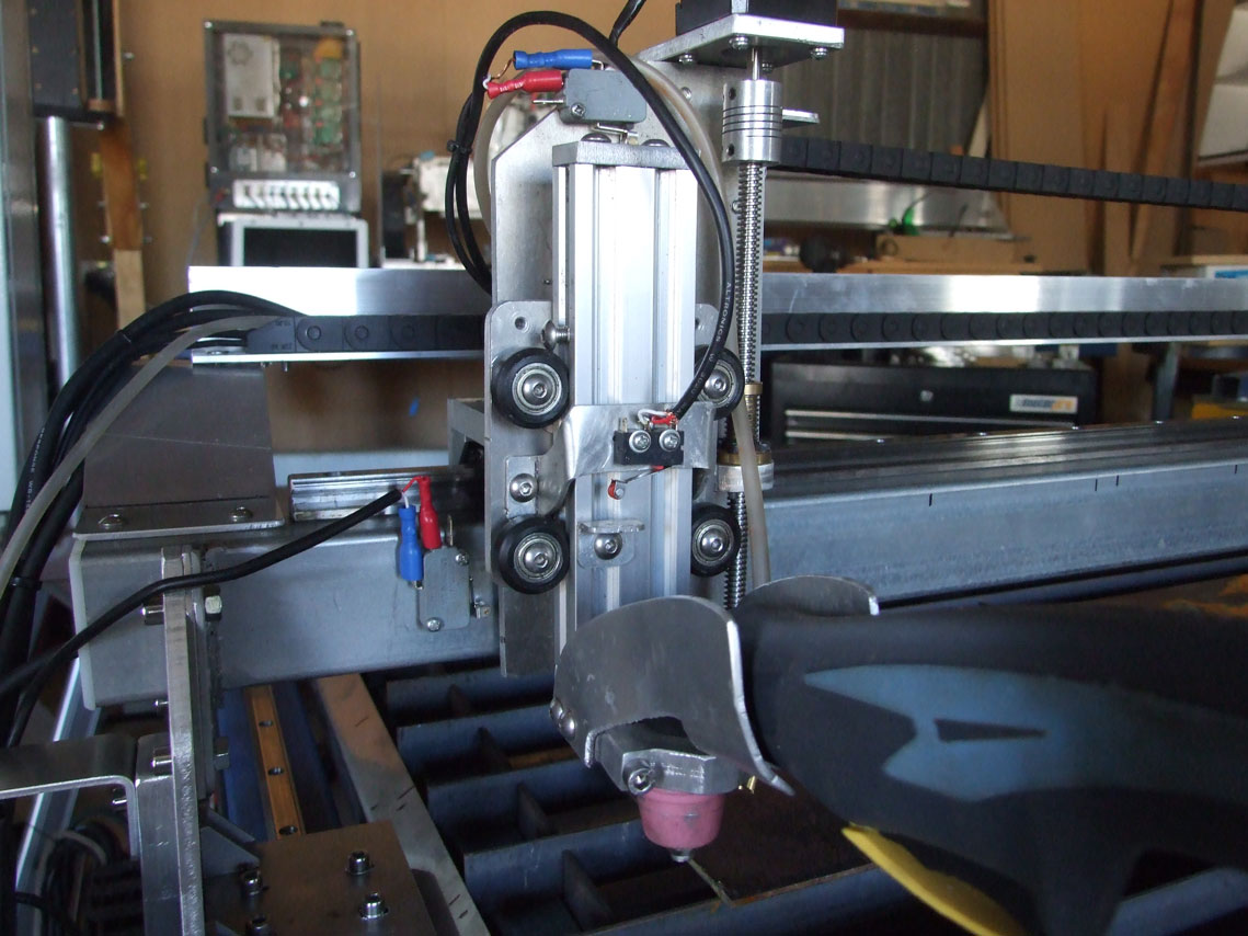
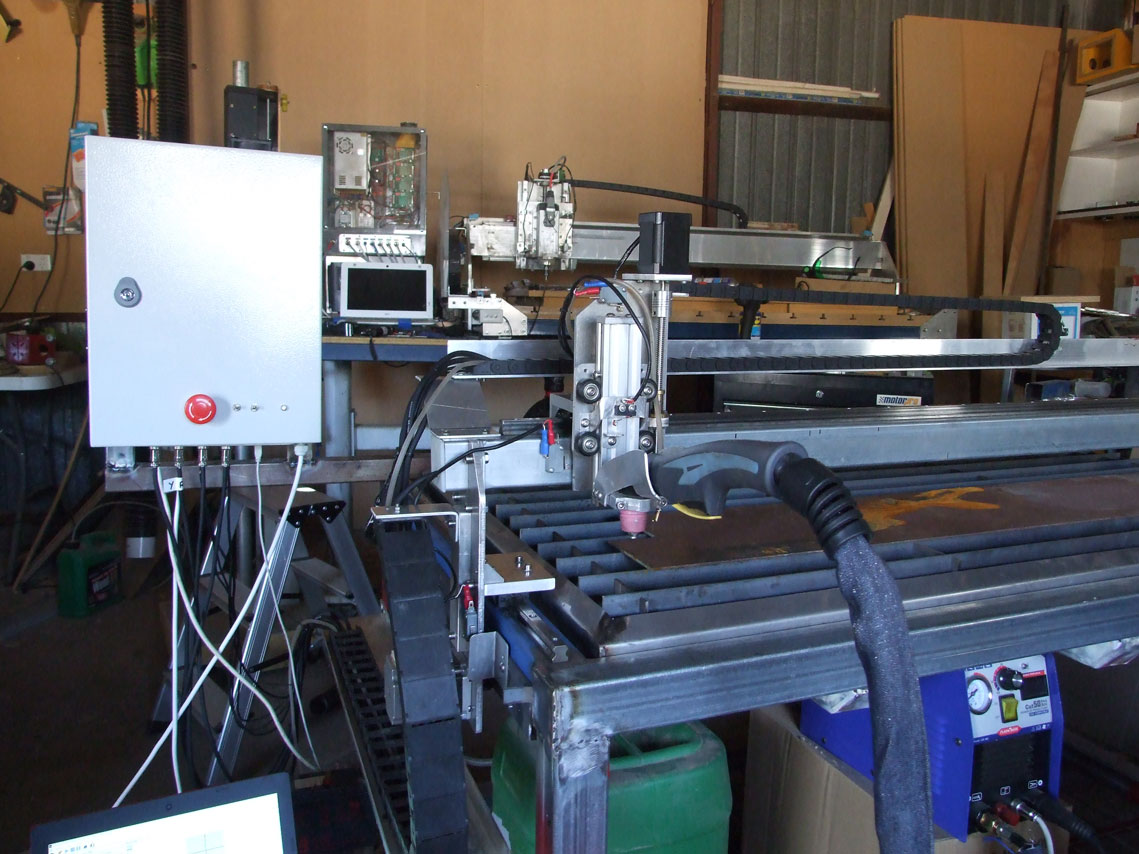
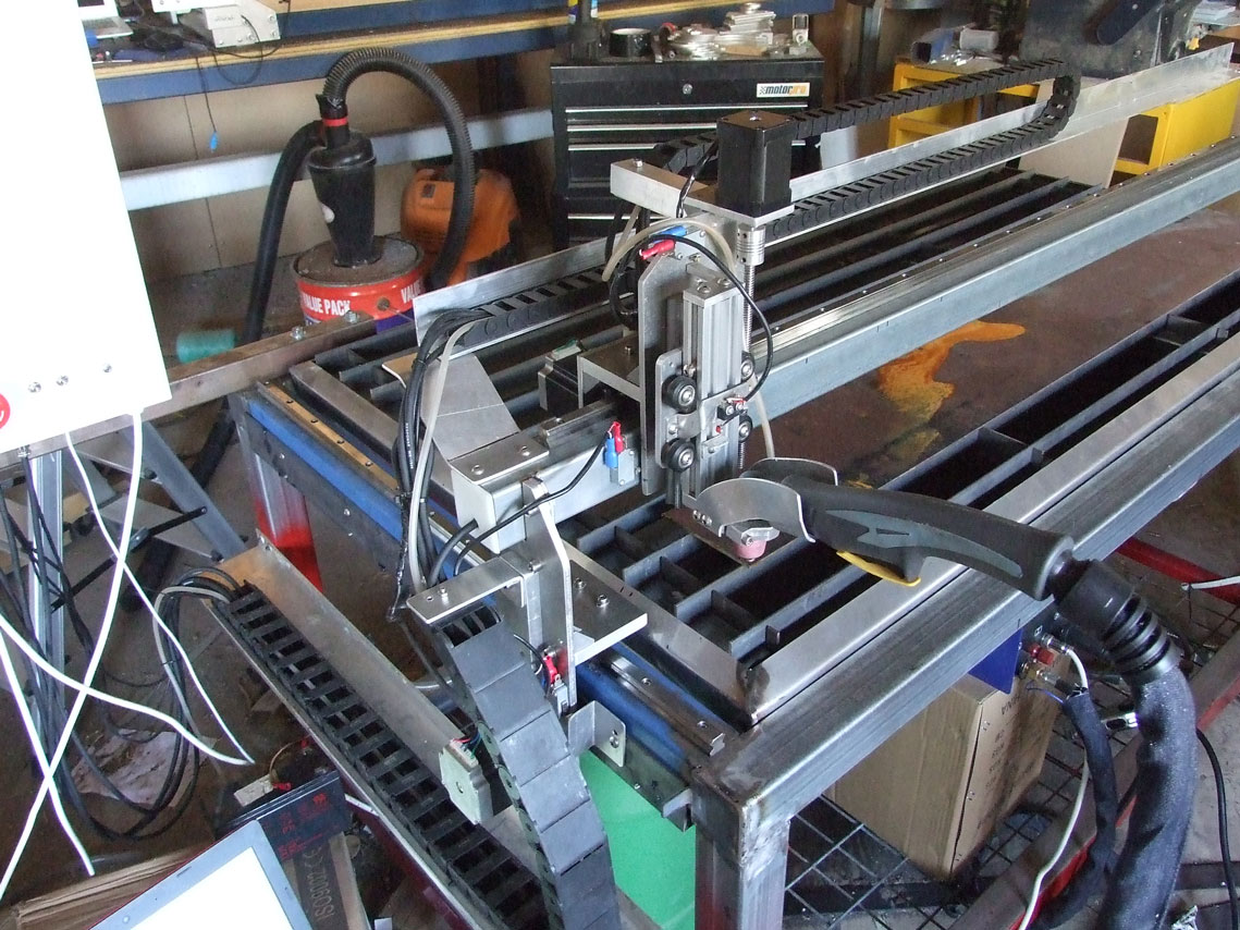
Here is a shot or two of the machine so far, it was built using the machine in the background that I designed and built earlier this last year. Both are using Arduino Nano for the controller and GRBL for the plasma and Estlcam for the mill.
Using sheetcam looks fairly simple, just need to get the right settings sorted out. Might do the first test cut tonight when the sun goes down.
I have run into another problem now.
Got all the movements working OK, manually zeroing the nozzle and did a test run without power to the plasma. All seemed to work OK.
Tested again with the plasma switched on and as soon as an arc started, the system shut down, so I guess I have some more shielding to do.
Will fit a line filter and some ferrite cores to the lines, all the cables are already shielded and the electronics are in a sealed metal box, everything earthed.
After I get this working I will have to figure out how to use the probe as I am not using that for now.
That machine uses HF start. You will need to pay a lot of attention to filtering and screening to get it to work as that HF will get everywhere. Make sure the only electrical connection to the table is at mains earth. Be careful to make sure none of your screens touch the frame of the machine.
Don’t attempt to measure the torch voltage with a meter. The cutting voltage should probably be around 100 - 150VDC but there is several thousand volts high frequency AC on the output when it is starting the arc. That HF is quite likely to destroy your meter. THC controllers have lots of built in filtering and protection to protect them from the HF. When you get to hooking up your THC controller you need to measure the voltage before the HF is injected. Open the machine (make sure it has been off for at least 5 minutes before you start) and look for a hefty coil near the front of the machine. It looks like a big spring made out of rectangular section copper. One end of this coil will connect to the output terminal. You want to measure from the other end. Negative can come from the ground terminal.
Unless you run out of speed on the machine, run at full current for all thicknesses. The faster you cut the less heat you put into the work and therefore the less distortion you will get. You will probably also get less dross that way. A rough by-eye way of checking the speed is to look at the jet exiting the bottom of the work. If it is straight down you are probably going a bit slow. If it is trailing at an angle of 45 degrees or more you are too fast.
At this point don’t worry too much about the kerf width. Take a guess at about 1.5mm (0.060"). Once you have made a few cuts you can measure the kerf. This value will vary depending on nozzle wear, material thickness and feed rate so you want to get the cut quality dialed in first.
Cut height is important. Did your torch come with a clip on guide for hand cutting? If so you can fit it on the torch and measure the cut height. That should give you a starting point. If not I’d go for something around 0.5 - 1mm. Make the pierce height about 1.5 times the cut height. Don’t worry about the touch-off switch yet. Manually zero the cutter to the top of the work until you have everything else working.
Thanks Les,
You have answered quite a few of my questions that I was puzzled about.
The plasma cutter was sold to me as being pilot arc, not HF, so maybe the Chinese don’t know the difference and probably don’t care either as long as they get a sale. (or is pilot arc the same as HF?)
I do have the shielded cables earthed to the frame, so I will rectify that, in fact all the earthing is sharing a common connection.
Not sure how I can isolate the earth leads though, because the power input earth is shared with both the plasma machine and the power input for the electronics through the mains supply.
I have an EMI filter that I will connect at the electronics power source and also have several ferrite EMI beads that I can fit to the leads.
The homing switches I have connected through opto isolators and also the probe switch as well (can’t get the probe to work yet)
Will read up on the Hypertherm cut speed recommendations info you have attached, thanks for that.
Pilot arc allows the arc to strike and maintain with the torch away from the surface. HF strikes the arc.
When I talked about the screens I meant that they should only be earthed at the box and not connected to the frame anywhere else.
Not sure how I can isolate the earth leads though, because the power input earth is shared with both the plasma machine and the power input for the electronics through the mains supply.
The shared mains earth should not be a problem. Basically you don’t want the earths to form a loop anywhere. If the screens touch the frame you have a loop: mains earth->control box->screen->frame->mains earth
Looking at your photo it looks like you are using connectors with metal shells on the control box. This is good - your screen should connect to the metal shell of the plug and socket should have a good electrical connection to the box (scrape off the paint around the fixing screws to be sure).
Thanks Les, I was a bit confused with your earlier post.
Yes the shields I have only connected at the box end and the mounting plate that holds all the aircraft connectors is metal and connected to the box too. The other ends of all the cables have the shields cut off close to the end and is not connected, so it will not be making contact with the frame.
The only cable that is not shielded is the trigger cable, maybe I should replace that one to be sure.
I downloaded a paper from the net by Hypertherm that talks about this problem and will try to follow what is suggested and keep in mind what you have said also.
As for the arc, I can press the trigger and maintain a steady arc when nowhere near the metal surface.
Well I don’t know what to try next.
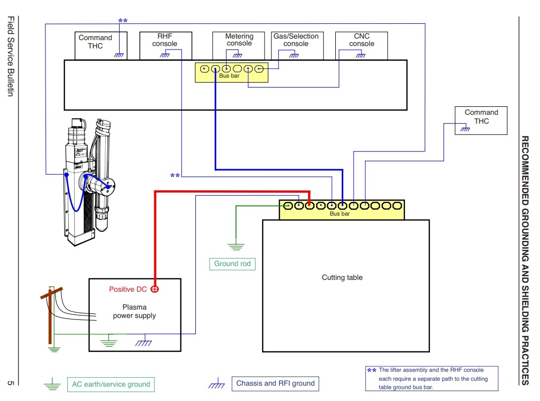
I have fitted all the earthing as described in the above diagram. Fitted shielded cables everywhere and only attached the shield at the control box end, other end free and not touching the earthed frame. I have fitted several ferrite suppressors and also fitted a EMI filter on the mains coming in to the control box.
I have tried without the limits being plugged in to see if the problem was coming from there and I also disconnected the probe as well.
All the stepper motors are wired with shielded cable.
The machine works 100% until I turn on the plasma, as soon as the trigger activates the processor shuts down at the first spark. I can run through a complete part in simulation mode, by having the plasma turned off, but as soon as I try to make a cut everything comes to a halt and I have to reset the processor and clear the alarm.
I think I will have a sleep on it and see what I can come up with tomorrow. I know others have been successful running GRBL and UGCS, so there must be something that I am missing, could be the plasma machine itself.
Is the controller connected to your computer via USB? If so the HF could be getting onto the USB cable and from there taking out the controller. Can you try running it off an SD card?
Thanks again Les,
Yes I came to the same conclusion, could be the USB cable.
Not able to run off and SD card unfortunately, I would like that.
After doing some research I found this info that may be the cure I am looking for, I have ordered the parts and will have to wait until they arrive before testing further. https://youtu.be/k3Q9S1hKPQc