I would like to know what are the Rotary plasma plugin (I,U-profiles) U-V-O cut order rules? My customers prefer web (V) section cut first and they ask me to provide that order in DGNest dxf export layout files. Is there any way how to reorder cut toolpaths without using “S” start positions in SheetCam? Is there any default cut order option in settings where I can choose: “Cut web section first”?
with menu Mode / ‘Edit start points’ selected, right click on drawing, select ‘Quick cut sequence’ and you can control the contour cut order within a layer.
And you can the cut order of Operations is respected if you want to segment contours by layer.
And see menu Options / ‘Job options’ / Nesting and select ‘Manual Optimization’ to reorder Parts and Operations.
‘Quick cut sequence’ is nice solution for small amount of parts. What when operator has 100 parts to cut? Some people have a problem to pick properly with mouse and stay focused on enumeration. My suggestion for SheetCam is to automatize cut sequence for Rotary plasma plugin, this would be very helpful.
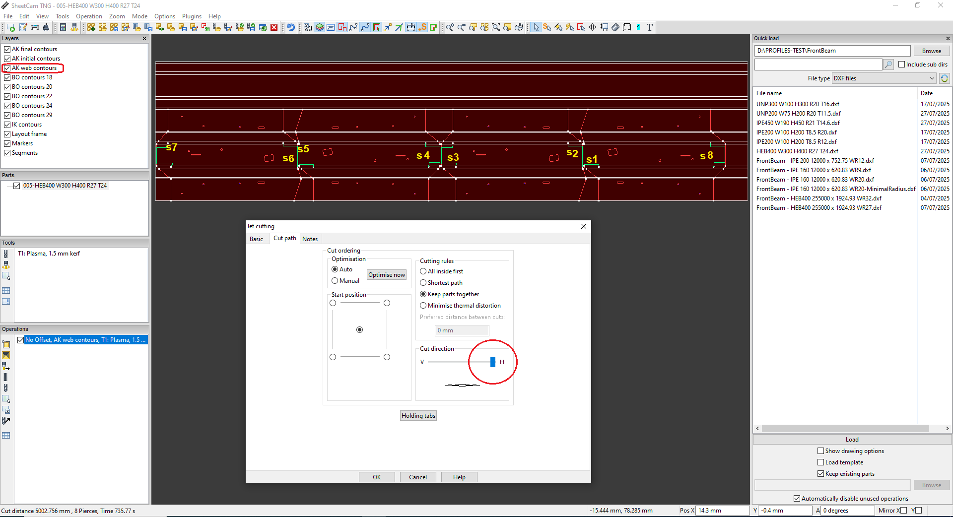
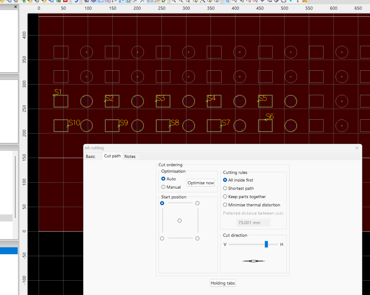
Sheetcam has several automatic cut order optimization features available. Let’s start with Operations / ‘Cut path’ dialogue. There are several controls and algorithms to select and experiment with. Similar controls can be found in Options / ‘Job options’ / Nesting which act on Parts/Operation packages. And of course the third is fully manual which is what you have discovered via Mode / ‘Start points’ / ‘Quick sequence’. Note the use of the Horizontal and Vertical sliders in the first two automatic optimization settings, this gives preference to those respective directions. In concert with all of these choices is the Layer element, which groups contours for isolation to specific Operations and tool choices.
It seems that if you’d like web shapes/contours cut first, then group those in a common Layer and set the automatic sequencing as needed. Then do the same with another group of shapes also kept in a separate Layer, and so on.
Another aspect of automation is controlling optimum placement of the start point, see menu Options / ‘Application options’ / Advanced / ‘Start point tool clearance’. If you find start points are tucked too tighly into sharp corners, increase this percentage to 300 or 400 and see the effect in the toolpath layout. Turn on Mode / ‘Show true width’ of kerf to see the reason why this occurs.
I will try, thank you!
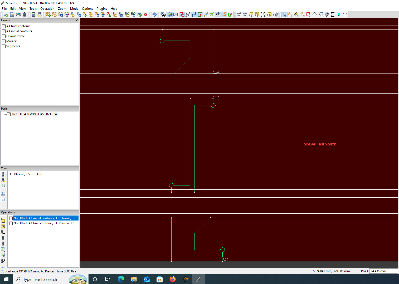
DGNest has a new layer (web contours for V-section of the I-beam). As you can see from the image I am using horizontal direction in Operations->Cut path and the same cut direction in Job options. Cut order is not as expected.
After ‘break up manually nested parts’ cut order is good S1-S2 but only on non mirrored parts, which is not good. I think cut order algorithm is not yet optimized for I-beams. Could you please send one example with 4 parts .job where you succeeded to make cut order on the web (V-section)?
Thanks,
Adam
That’s it: start position top-left. Now it works well. I have had to split my web layer into two layers: web initial and web final and swap mirrored cuts (initial-final)
Thank you!
Adam
008-HEB400 W300 H400 R27 T24 .job (297.7 KB)
1 Like