I have been using sheetcam v7.0.21 for about a year. It’s been easy to use, free versiion, but today the program stopped cutting the interior cuts first. Most of my stuff is really simple. I’ve made sure the operation is set to cut interiors first but it isn’t working that way. It cutsw the perimeter first. Any suggestions?
cut (toolpath) sequencing by default is controlled by the following (I believe it’s a complete list), and note that these controls persist across different jobs.
- order of Operations,
- within Operations, choices on the ‘Cut Path’ tab,
- Options / ‘Job options’ / Nesting where Parts and Operations can be reordered.
There are more controls, but you have to deliberately use them and they don’t persist across jobs.
cut path tab was the first place I checked. I’ve done over 100 cnc files since I got the plasma table.
It’s always worked. I import the file, activate the operation (two clicks, open and ok), then run the post processor. my designs are simple. I never have to change anything, but now the operation is to cut the outline first. I’ll look at nesting, but not sure I saw anything there previously
upload your job file and post processor file here and the user community can have a look.
It could be that your outline shape is an open contour, or any number of other reasons. At this point, it’s easiest to just upload your job file and pp.
I was denied upload because I’m a new user
I tried to upload to the email, but it was a no-reply email.
But the files are simple, I made one perfect after another. I modified a dxf file with a slight movement of one node or point by .003” and now sheetcam won’t cut interiors first.
I’m thinking maybe I need to uninstall and reinstall the program or somehow set the program back to default
@irontree , your id has been boosted to allow uploading now.
leaf -12.8 inch-mod3-10 degree-ro-test.job (4.6 KB)
leaf -12.8 inch-mod3-10 degree-ro–test1.cnc (478 Bytes)
After reviewing your job file, here’s what I find… the primary cause for the wrong cut sequencing (cutting outer most shape first instead of last) is that your outer-most shape is an open contour, therefore there are no ‘inner shapes’ to cut first per the ‘cut rule’ selected by that name in the Operation on the ‘Cut path’ tab/window. A closed shape/contour is needed first in order for sheetcam to even search for ‘inner shapes’.
Sheetcam provides some clues that you have open shapes/contours in your drawing, but you have masked off those clues with cut options and definitions that you have selected in the Operation, and perhaps with settings for visual clues.
re. Operation cut options and definitions-
- you are using ‘Offset open paths’ option presumably to mask off the warning symbol (yellow triangle) and msg that ‘Open shapes are not offset’. When you get that warning msg in the upper left corner of the drawing canvas, hover your mouse pointer over the msg and the drawing will zoom to the open shape(s), which in your case is the full drawing since the outer-most shape is open. Not the best method, but it will draw your attention to most cases.
- you are using a perpendicular leadin of just 0.003mm, indistinguishable without a drawing zoom level of 1mm scale for the whole screen, and coupled with option ‘Leadin on open shapes’ selected. A standard leadin of 4mm or so would clearly show which toolpaths are open as you toggle that option. I suspect you don’t want a leadin on open shapes which is why you have 0.003mm defined. So that is one way to clearly recognize open shapes.
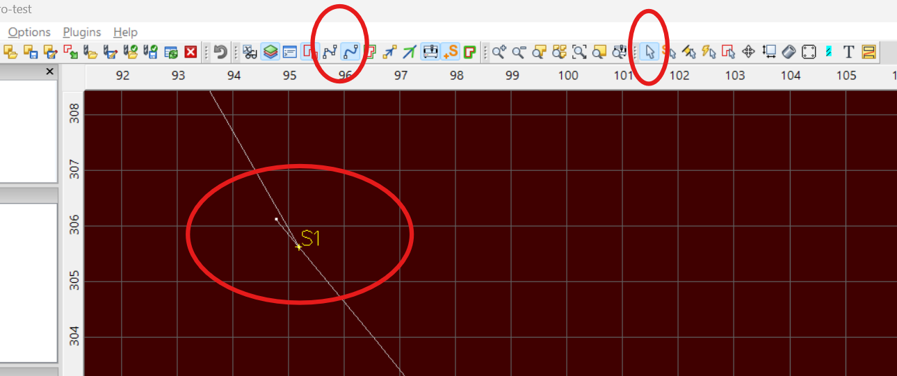
re. sheetcam Toolbar View settings that can help find open shapes- View / ‘Show path ends’ = ON + ‘Show segment ends’ = OFF. Also, note that open shapes/contours are by default white color, while closed shapes/contours are red (outer) and yellow (inner). Thus open shapes can be identified when you see white node (dots) at the two ends of a white contour. You won’t see any nodes on a red or yellow closed shape, with the settings noted above. Note you should be in Mode / ‘View toolpath’ to see the contour colors as described here.
I need to look this over closely. That same dxf file without any changes worked fine in the previous cnc conversion, as did all the others until “mod 4”. Thank you. I know very little about all of the intricacies of the sheetcam program. Wouldn’t I have had to open up the perimeter in the dxf drawing to cause that open perimeter? The reference to the .003 change was only a movement to extend one corner of the shape it didn’t open up the perimeter. Would it be of any benifit if I were to upload the dxf file to you?
sure enough. I just saw the missed point that caused the open perimeter in my mod 4 drawing. I should have taken note of the color change in the drawing in sheetcam.
Thank you again.