Could you post an example job file here on the forum so I can take a look.
I use a modified by me post Mach3 plasma. The code for THC are M10Q255 and M11. I put them with a space forward to be seen easily.
triagalna.tap (1.15 KB)
triagalna.job (6.83 KB)
I found one problem. In your ‘On small shapes’ rule you have your start code and end code both set to ‘thc off’. This will output more THC off commands than you expect.
Is the ‘THC on’ at the end of the cut a problem? This is enabling the THC ready for the next cut. If this is causing a problem for you, you could add a THC off command in your OnPenUp() function in the post.
I have grown the THC to work extremely fast, and when this happens, it switches on just before the plasma stops, and then the Z axis travels about 3mm downward to activate the anti-collision sensor. That is why I use only some rules and manually set the action point where it is needed. That’s why I opened this topic too. If I myself could program a python so far I would have done it and I would not have persuaded you how much it would make it easier I would just suggest it for you.
In the end, do you think it is so difficult to make such an algorithm that, if it is set at a minimum distance, divides the internal shapes and the contour into parts where the direction is changed for a distance less than or equal to the specified distance. It does not matter whether it is an arc if the arc R is less than or equal to the minimum distance or angle. So it automatically adds this distance before and after these zones and there we have THC Off.
In the beginning after the start THC is again Off until the zone after the Lead in + minimum distance then THC becomes On. So follow - minimum distance + angle + minimum distance, … to the end where there is a minimum distance + Lead out. I hope you understand me ! ?
This is exactly what rules were designed to do. The only problem you seem to be seeing is that it turns the THC back on at the end of the cut. As I said it is easy enough to modify the post to turn it back off again.
I start thinking that you do not understand what I mean and what is valuable in what I offer, so I will try to analyze the rules that you have created:
1.After start - this rule is not done well because it does not conform to the Lead in length and should always be changed! If it has to be configured as THC Off-Off, it does not make sense for it.
2.On Lead in - enters into a conflict apparently with the arc rule if Lead in is an arc - also not a good enough solution!
3.On corners - the fact that there are three rules for corners is a bad decision because it complicates logic and makes ambiguous assumptions about what exactly they are serving!
4. On small chapes / circles - the fact that here again two rules is also strange and unclear!
5.On arcs - conflicts with both Lead in and Lead out if they are arcs because the logic is different!
6.Near pierce - I have no idea what this rule is intended for!
Now let’s imagine that these rules replace them only as a variable - a minimum distance! This distance will be determined experimentally on each machine by the way I described earlier and the post will be included in a formula to proportionally increase this distance along with the change of F.
And finally, I make the offer completely free without expecting anything in return. For me, it’s important for people who like Sheetcam like me to enjoy the program even more easily and with no effort and nerves !!!
Hello, Les you think about a poll in the forum about the cutting rules. Allow it to evaluate each of the rules.
Such a poll could give rise to a topic with suggestions for improvements and help you rethink some things.
Go ahead and make a poll. Go to the new features forum and select new topic. At the bottom of the text box you will see a tab that allows you to create polls.
Interesting thread. I use LinuxCNC which is coming ahead in leaps and bounds with plasma. Its taken a couple of years of hard work to show people what can be done in LinuxCNC if you forget the paradigms set by Mach3 and external THC’s when we have access to the trajectory planner and the full power of a 64 bit CPU running a real time operating system at our disposal. For example, the Velocity anti-dive feature is a trivial exercise requiring about 10 lines of code.
I have to say I had some issues with sheetcam rules for arcs and looked for other solutions. Earlier this year, with some help in the community I identified a couple of mathematical techniques that could be used by a LinuxCNC component to dynamically calculate the radius of an arc as it was being cut at a rate of 1000 times a second on the LinuxCNC servo thread. I coded one of these methods and concluded it did not work. I have not tried the second method which emerged after I started and appeared to have a greater probability of success. I got a bit distracted modifying my table to support ohmic sensing (which was a bigger task than I first thought) but you’ve reminded me I must revisit this idea.
Our current experimental open source plasma config with internal THC is already regarded as rivalling high end commercial systems and streets ahead of the run of the mill external THC units mentioned here for Mach and UCCNC etc. I don’t have any experience to make a call on this.
I’ve disabled all the sheetcam cutting rules I was using and depend on the antidive feature but I think it would be cool if I can crack the arc radius calculations at the system level outside of the post processor and Gcode as some sophisticated algorithms would follow pretty quickly! One of the issues I had was chain cutting holes in 16mm plate. Slowing the cut for holes was useful but for this job it had to be done on arcs and then it caused problems in sections I did not want to slow down.
First of all, I want to call my colleague that you are on the right track with the Linux CNC. We are also working in this direction and I hope we will soon have a decent result. Look at what I wrote about determining the distance that is critical for changing direction on your machine. Then, if you have enough knowledge to experiment with hall-level LinuxCNC, then you can also take a look at the Python features.
Using free python software, you can analyze each contour and divide it into parts as well as add parts automatically. Part that is a lead in, a part that is executed at a speed other than 100%, a part that is at maximum speed then delay again and so …
Only in this way can you get a good job. Of course you can always experiment with the M10 / M11 and the time that there are no accelerations and delays that the LinuxCNC can include in real time.
I myself after many experiments with ohmic contact I gave up the complicated circuits and now the machines do them only with a 24 volt circuit and a separate relay power supply is a separate adapter for $ 5. This relay switches on when the burner touches the material and closes the input sample. which can be damaged costs $ 6.
It was not so much the ohmic sensing that took time but to implement it required replacement of the drag chain to make room for a larger torch lead and the ohmic wire. We use 3 optoisolated relays with 24 volts on an isolated power supply. and some 1000 volt diodes. 2 relays and diodes are used to isolate both legs (to torch and table) until such time as we actually want to probe and the second switch field power to an ohmic sense input.
Anyway you spurred me on and I revisited method 2 and solved the maths last night but have not experimented to see if the calculations will result in a workable solution. I will mention you could follow the same approach in the Sheetcam onArc() method where a bit more is known about the trajectory so it would be easier.
Yes, one solution suggested was to create a filter on the gcode files that ran as they were opened and modify the code in python. This was not something I wanted to do because with sheetcam in the mix it is more efficient to control this in the generated code where the post processor provides you with hooks where you can modify the code as you’ve described. With LinuxCNC we use M64/M65 which will toggle a pin on and off to enable/disable the THC instantly. Making decisions about cutting speeds will never be perfect from gcode as the laws of physics will prevent attainment of desired cutting speed on short segments at the trajectory planner when the code is parsed. Also, the code is parsed in a read ahead buffer so the interpretation may be a long way ahead of the actual motion so its not possible to physically map the two in real time.
I really would encourage you to get to know the sheetcam post environment. A lot of what you want to do can be done there.
I have the feeling that you did not understand what I mean! Analyzing the contour that can be done by python software does not just recognize the parts of the contour, you know? It creates new parts that are running at different speeds. These new parts of the loop will be executed in a stream at a constant speed. So can be predicted how they will be executed by the CNC controller. I think there is no point in discussing, the controllers that can not run in motion and see ahead in the code. They do not work right anyway, right?
For the ohmic contact - the separate adapter is very important. So there is no need to protect the relay from the voltage of the plasma because its ground is different and the current does not flow!
It might sound nice but it certainly can’t be done in LinuxCNC becasue LinuxCNC IS_THE_MOTION_CONTROLLER.
In Mach and other systems the motion controller is external to the PC. Eg an ESS smooth stepper board.
LinuxCNC has massively more resources at its disposal than these external boards (via a 64 bit CPU) but it has to run on a real time version of LinuxCNC.
The core of Linuxcnc is executed on the servo thread which is guaranteed to run exactly on time without fail by the Linux real time kernel. Usually this is running at 1 kHz but can be faster if the situation demands it (and your hardware is good enough)
Because Linuxcnc is the motion controller, as system integrators, we have full access to the servo thread. That is not possible with external motion controllers that only exist because Windows is not a real time operating system.
Python is an interepreted language and can’t execute in Real time. It runs in LinuxCNC’s user space where timing is not enforced. its not possible to predict whats going on in real time via the Python Interpreter.
Gcode is an interpreted environment
Motion is a real time environment
Gcode is parsed and tokenised in a buffered environment in accordance with the RS274ngc standard. Then the gcode thrown away as it serves no further purpose. Then the motion controller determines if the commands can be executed having regard for the laws of physics and the machine’s velocity and acceleration limits. eg on short segments, honoring the commanded feedrate may not be possible. To say you can predict the motion from an interpreted language is simply not possible as you don’t have a motion controller at your disposal and you are not operating in real time.
There is a reason why Tormach and CandCNC have migrated away from a Mach environment in favour of customised versions of LinuxCNC. It simply superior in all respects. I can assure you it works right!
Could you explain in a bit more detail what your arc method entails.
I had a thought earlier - would it be enough to turn off THC if the machine’s acceleration exceeds a given value? It would be pretty easy to write a LinuxCNC hal module to work out the current acceleration and trigger an output when the acceleration exceeds a given threshold. This would trigger when cutting sharp arcs and when approaching corners.
Les, yes, doing a corner lock in a linuxcnc component is is pretty trivial code . Here is how I did it. But there is one gotcha here
author "Rod Webster";

pin in  float current_vel                "Current Velocity (motion.current-vel)";
pin in  float override                   "Current Override (halui.feed-override.value)";
pin in  float cut_vel                    "Desired Cutting Velocity Units/min)";
pin in  bit enable = 0                   "Set TRUE to enable corner lock";
pin in  bit override_is_pct = 0          "Set TRUE if override value is a pecentage, FALSE if it is a fraction";
pin in  float threshold                  "Percentage of Cut velocity that triggers corner lock hold (1-100 percent)";
pin out float min_vel                    "Calculated minimum Velocity (from cut-velocity)";
pin out bit is_active                    "True if Corner lock is enabled and holding";
pin out bit override_is_active           "Convenience, TRUE if feed override is set";


function _;
license "GPL";
;;

#include <rtapi_math.h>

FUNCTION(_) {
  double override_val = 0;
  if(override < 1.0 || override > 1.0)
    override_is_active = 1;
  else
    override_is_active = 0;
  if(enable){
    if(override_is_pct)
      override_val = override / 100.0;
    else
      override_val = override;
    min_vel = ((cut_vel*override_val)/60.0)* (threshold/100.0);
    if (current_vel <= min_vel && current_vel != 0)
      is_active = 1;
    else
      is_active = 0;
  }
  else{
    min_vel = 0.0;
    is_active = 0;
  }
}
The gotcha is that there is no way to get the commanded velocity which is set by the F code. The motion.requested-vel pin is set by the trajectory planner for that particular segment. This can be significantly lower than the F command if the trajectory planner is unable to honour the users requested velocity. Gcode can send a number back to Linuxcnc HAL using M67/M68 so you either need to call that on every F command in POST or a better way is to REMAP the F command using the standard LinuxCNC python remap method (there are included sim examples to show how this is done). There is a branch called state tags which if adopted will create a new tag structure so data like this can be retrieved in HAL.
So my arc idea was to monitored the motion.motion-type pin which tells us if we are cutting an arc. I surmised it might therefore be possible to do some maths to calculate the radius of the arc in real time. Andy proposed a method based on circular velocity. This was able to accurately determine the current velocity but I had no luck getting consistent results for the radius. As you can appreciate, its hard to debug things in a component on a 1kHz servo thread!
Then an alternative method was proposed just using basic trig solving for the radius of a circle passing through 3 points. My first attempt at this failed because I could not find or solve one formula. I found what I was missing. It sounds like a better method but my time is limited right now so I have not revisited this.
I have to say many components of an advanced THC can be written in small components such as what I’ve shown. Sampling torch voltage is just as trivial but you need to hold off until the machine is near the F code velocity for the reasons discussed above.
That’s why I suggested monitoring the acceleration rather than the velocity.
The basic code would go something like this
pin in  float current_vel                "Current Velocity (motion.current-vel)";
pin out bit is_active                    "True if Corner lock is enabled and holding";
pin in  float threshold                    "Acceleration threshold";

variable float lastVel = 0

FUNCTION(_) {
double accel = current_vel - lastVel;
lastVel = current_vel;
is_active = fabs(accel) > threshold;
}
The above is completely untested and just to give you an idea of what I mean. Ideally you want to scale the calculated acceleration by the actual period to allow for timing jitter.
Initially, I thought your idea could work becasue if at the commanded feed rate acceleration will be 0. But on a short segment at say 80% of the F command, I think it might see the change in acceleration and trigger spuriously. Thats why we started to use remap becasue when we just worked on motion.current-vel, there would be divots in the cut because the machine thought it was at cut height but the voltage was way too low so it would correct height violently when it shouldn’t.
Don’t get me started about pauses by the motion planner with changes in direction but that ones been fixed.
You could put in a timer to ignore very short accelerations. If it only decelerates for a short time the speed won’t have changed much.
I think I will refuse to offer because it is not clear what the benefits of what I offer.
That’s why I will ask again - if the software succeeds in dividing the contours and the islands and the holes in this way, What is the problem with the CNC controller to execute the movement and the red plots stop the THC?
THC.pdf (6.82 KB)
Well for the most part the corner lock/velocity antidive code I posted together with a THC on delay will solve your problems without need for any other complexity.
After extensive data collection using Linuxcnc’s software oscilloscope (halscope), I have found that a THC on delay of about 1.5 seconds after arcOK seems about right for the initial establishing spike in voltage to subside. This is 8mm mild steel at 80 amps. E:feedback is arc voltage and E:arc-ok is the arcOK signal and we sample the arc voltage when the THC is enabled. If the current velocity is not near commanded velocity, we wait until it is before enabling THC and sampling.
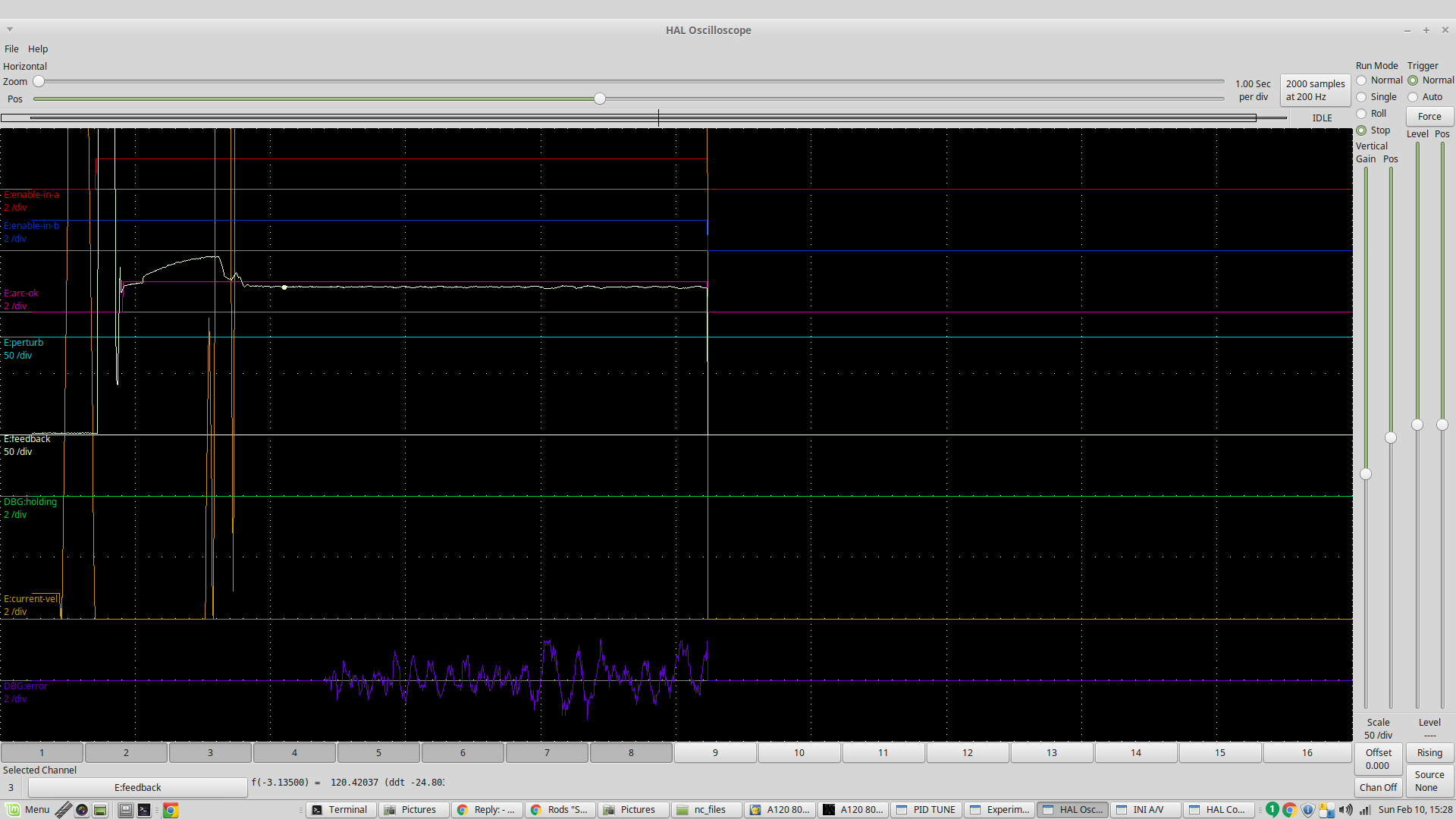
You can see the THC is enabled at the point where the blue error line starts to be plotted (1.5 seconds after arcOK goes true). This period could be shortened a bit in this instance but 16mm thick material is a bit slower settling.
Lets look at your simple square. The leadin will mostly occur within the ArcOK delay and there will be a ramp up from 0 to your cut speed based on the trajectory planner logic. After 1.5 seconds, the THC is enabled and the arc voltage is sampled. Torch height is now under THC control. As the cut approaches the corner, the trajectory planner will reduce velocity in preparation for the change of direction. Once the velocity falls below the threshold (say 90% of commanded velocity after allowing for feed overrides), the THC will be disabled. The corner is negotiated and the trajectory planner accelerates back to commanded velocity. Once it gets over our 90% threshold, THC will be enabled again. As the cut is completed the TP will slow the cut speed and the THC will be disabled at the end of the cut
Looking to the inside cut rectangles, the same rules would apply. THC would most likely be enabled becasue some of your long side cuts would be at speed. There is no reason to slow them down.
Circles are mostly self managed by the same logic becasue the trajectory planner is unable to get to cut speed so the THC is never enabled. You can augment this with Sheetcam’s automated cut rules and tie the cut velocity to a percentage of circle diameter based on different sizes. This is quite useful and would solve your problems on the bottom right. Maybe the large hole is cut at 80% of cut speed and the smaller ones cut at 60% with those rules.
The problem I had was with arcs on chain cut holes in 16mm plate. Lets look at the example on the top right again as the corner arcs are similar to what I had. You have 3 arcs on the outside corners, transition in, circular cut and transition out. I would be quite happy with the cornerlock managing the transitions. But I found I could not set up a rule in sheetcam that ignored small arcs and modified the circular cut. This is what led me to explore the possibilities of calculating the arc radius in real time (eg 1000 times a second). This would allow me to build much more sophisticated rules to modify cut speed and THC enabling than sheetcam provides. Time will tell if I can achieve this.