Hello all.
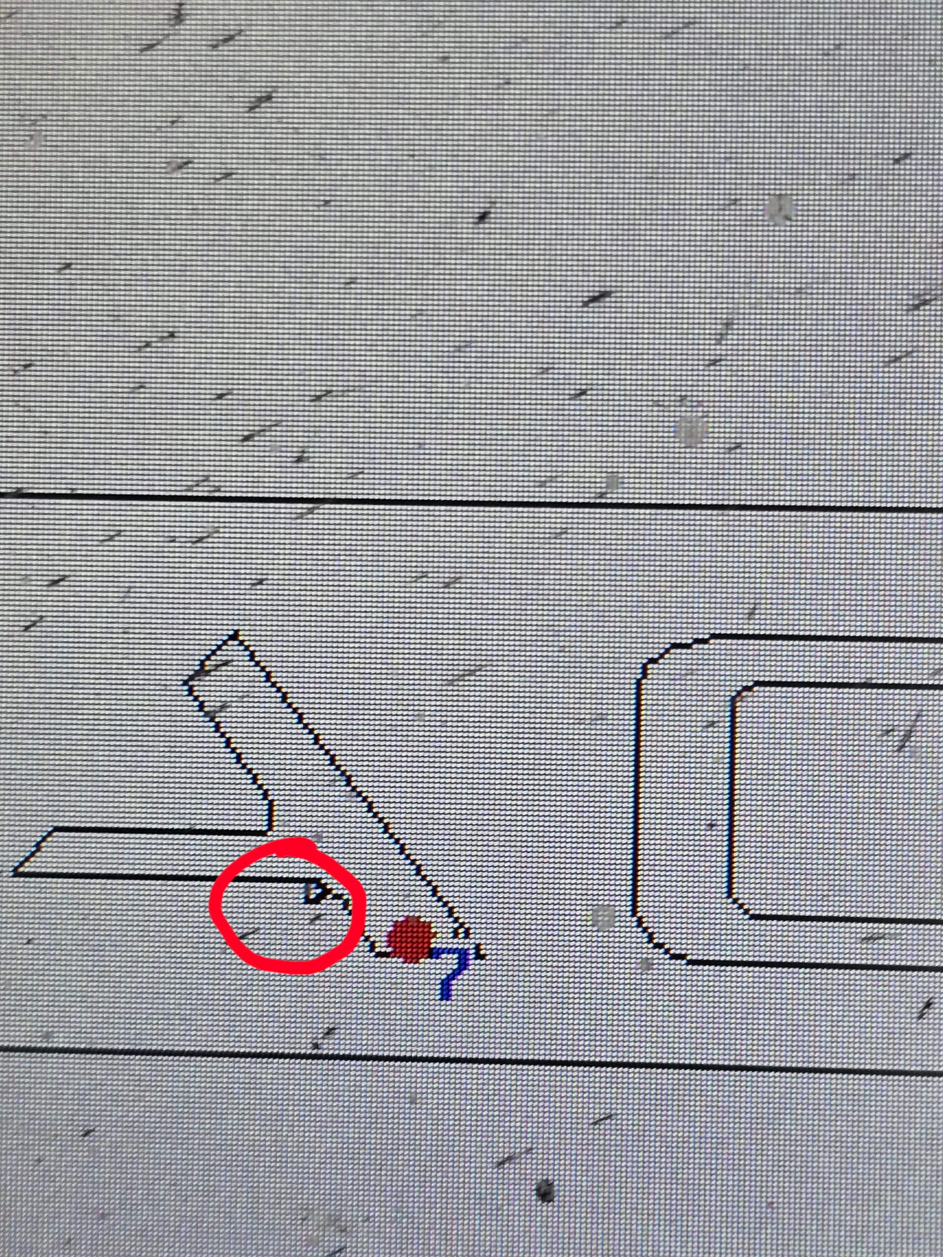
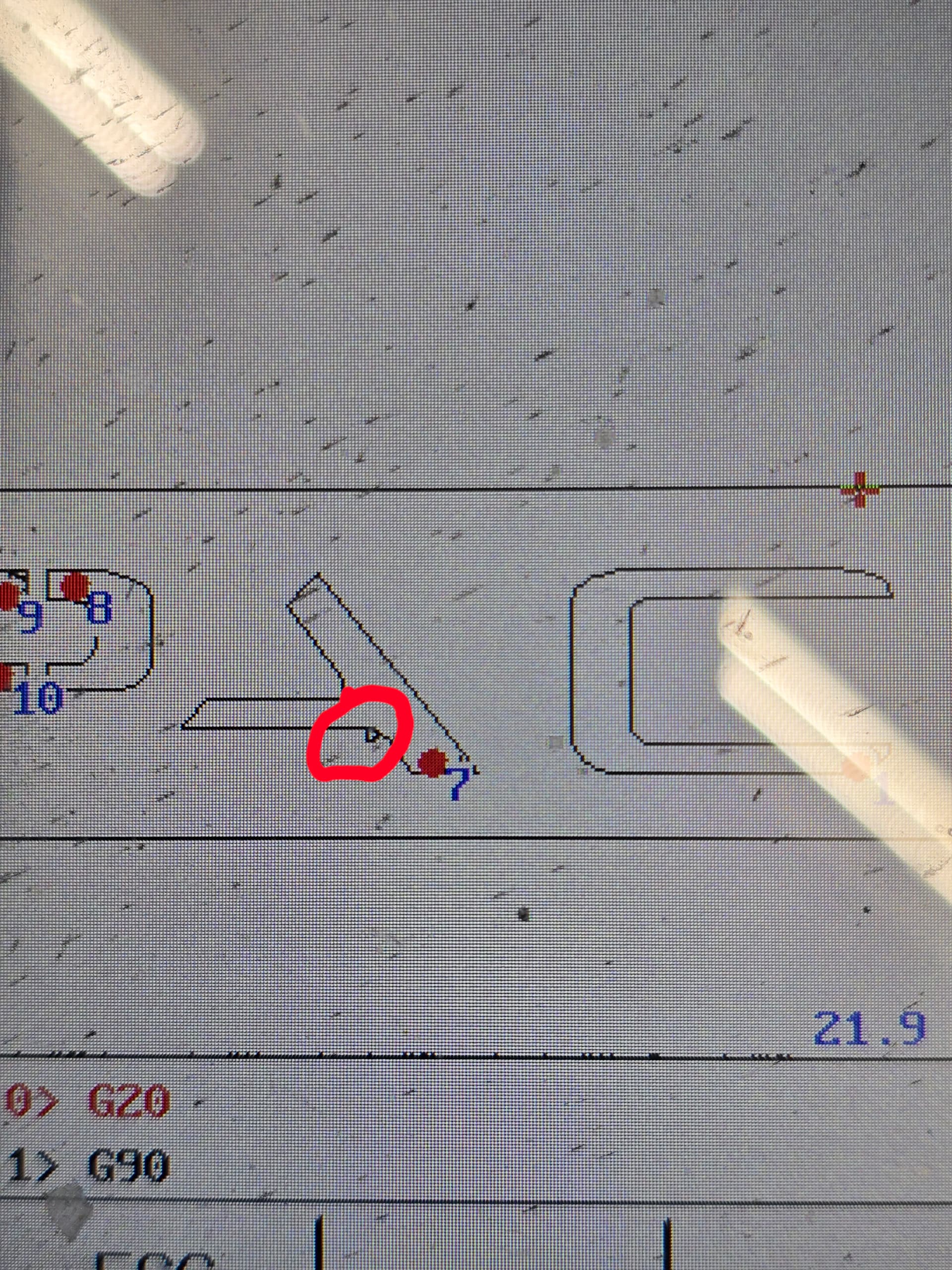
I have a strange issue that seems random. When I generate a cut path in Sheetcam I always take a zoomed in look after I run the PP. My cut paths look good. So I will save it to my thumbdrive. I have to change the file extension from ‘.tap” to “.cnc” so the table will read the file. When I open the file on the table console there are little deviations in the cut path that show up in random places. These deviations look like a little divot off of the cut path. Maybe a better term is a little notch in the cut path. The cut path is still there, but there is an additional little spot that is the size of the kerf.
After I noticed it on a few pieces, I zoomed in on the image on the machine screen and sure enough, there is a little notch or spot where the cut line moves off then right back to the original line. I have no idea why this is happening. It is random and not consistent and it does not happen every time. I need to see if anyone else has experienced this.
My courses of action is to reload software for the machine as well as the firmware. I am not sure if this is a Sheetcam issue or an Eastwood software issue. All I know is that I am ruining a lot of pieces trying to get this figured out.
So far I have also had a friend run the pieces through Fusion 360 and there have been no errors.
Any assistance would be greatly appreciated.
Thank you all so much
Tommy
This sounds like cutter compensation, which I believe Eastwood tables w Fangling controller have the capability to do. I sent you a DM with some instructions, I’ll wait to hear from you.
Lou
Lou,
I will send you the information this evening via the email address you provided. I am at work currently and do no have access to the machine right now. Thank you for the rapid reply though!
Tommy
Update
So I did send the information to Lou from my machine. I tried a different PP from Eastwood…NO Bueno
I tried the PP from Halo Innovations because they are the same table as the Eastwood. NO Bueno
Reading in some of the forums here I saw a post that is referencing the Fangling controller. A poster said he used the Hypertherm Edge PP. So I did that. Partial success. What happened was there is a scaling issue with that PP and my table. My 21” x 4” image was reduced to a couple of MM. So Scaled up in the table controller by a factor of 30 and got a perfect cut.
This tells me there is something in the Eastwood PP that is introducing this artifact OR there is a setting I have incorrect in my sheetcam software.
@okedodge
After reviewing your support.zip file, the problem is in your pp, you’re using ‘cutter compensation’ G41 gcode, and your controller has a setting for the compensation amount which is causing the toolpath to jog off the contour path. You should always run G40 gcode which is ‘no cutter compensation’ mode. Then it doesn’t matter that your controller has a cutter comp offset value. Sheetcam fully accounts for the kerf width by the definition of such in the Plasma Tool.
Here’s a snip from your gcode file showing G41 active while cutting…
G20
G90
G40
G00X10.8593Y0.5328
G41
M07
G03X11.0399Y0.5199I0.0968J0.0838F72.0
...
I have fixed your pp to NOT use G41, please use the version attached.
55132 Eastwood Elite CNC Plasma SheetCAM Post Processor G40 only.scpost (2.1 KB)
update: perhaps to be more clear re. “always run G40”… ‘always’ should be qualified with, “unless you are fully aware of cutter compensation G41/G42 vs. G40 and intend to use controller managed cutter compensation values correctly.”
Cutter comp can be useful when dialing in the left or right offset of the cutter to the shape contour, such that the Part which is cut is exact to +/-0.0005” or better. Now it won’t be possible to get plasma jet cutting to that accuracy just due to the jet dimension being wild and rapid wear factor of the nozzle. However, water jet, laser, milling bits… those can be dialed in like that. Water jet may be similar to plasma jet in terms of rapid wear factor and wild kerf, I don’t know.
Net: use cutter compensation carefully, with any CAM. As for sheetcam, keep the cutter comp offset value in the console to less than 20% of the overall kerf width as defined in the sheetcam tool, else strange side effects will occur in the toolpath for sharp corners, leadins, etc. Direction of cut matters in terms of use of G41 (left comp) or G42 (right comp).
Sheetcam has 3 undocumented pp function actions to handle use of cutter comp, but you will likely need some conditional logic within the functions to manage the gcode posting for the correct circumstances.
function OnOffsetNone()
  post.Text(" G40 \n") – cutter compensation off
end

function OnOffsetLeft()
  post.Text(" G41 \n") – cutter compensation left
end

function OnOffsetRight()
  post.Text(" G42 \n") – cutter compensation right
end
I see the code you added.
I will look at my machine this evening and see if there are any settings I may have changed while setting this machine up.
I appreciate you taking the time to help. This makes all the difference in the world.
uuummm…. be careful with making changes in the Fangling console, many settings are time units which then translate to Z motion, and things can go south quickly. If you plan to make changes to settings, make a backup file of the current setting values so you can always regress to current state.
See this thread for a Fangling assessment related to time unit settings - https://plasmaspider.com/viewtopic.php?t=38004
Thank you for that. Yes I am well aware of how a small change alters the outcome. I am new this area of technology, and learning rapidly. I love how the community comes together to assist.
Thank you for the link. I will read it for sure.
Tommy