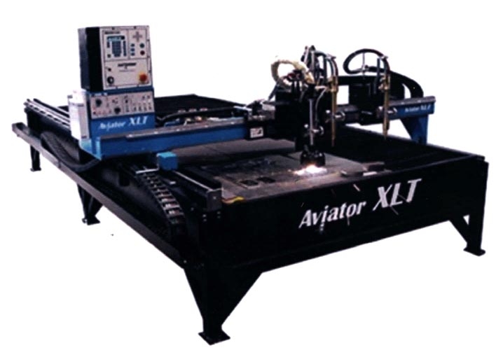
Burny 1250 +

First off, thank you Sir for creating this time saving masterpiece!

The plasma table we are currently working with uses a Burny 1250+ controller. We are using the Burny 2.5 post and it seems to work. Also
using Sheetcam 3.0.7 with Win7. Compatibility mode is set for your program to XP pro sp3

One issue is on the last rapid to the park position after the cut process, the torch stays on and cuts as it moves. We have to move the M03 up one line in the gcode to prevent this. It has also happened on the first rapid before which destroyed the part.
Is there a way to disable the rapids from and to park position?
The last rapid to park does not show on the screen even though it is in the gcode and the simulator doesn’t run it either.

Is it possible in the simulation that in the gcode editor box, each step could be highlighted as the simulator performs that command? It sure would help to better understand what each command does.

Thanks Les!

:smiley:

I can’t see anything obviously wrong with the post. Are you using a registered version of SheetCam? If your copy isn’t licensed then it may leave the cutter on for the last move if you hit the evaluation limit.

The move to park position has been hard coded into the post which is why it doesn’t appear in simulation. Go to Options->machine->post processor and click on the ‘edit post’ button. Look for this chunk of code:

function OnFinish()
   endX = 0
   endY = 0
   OnRapid()
   post.Text ("M30\n")
end

Change it to:

function OnFinish()
   post.Text ("M30\n")
end

I am afraid the simulator can’t highlight the code as it runs. The problme is that every post processor generates different code. It would be impossible to make the simulator understand the code from every machine. Instead it generates it’s own code which (isn’t even G-code) and runs that.

We are running the evaluation version. We are thrilled with the results of your software and your quick response is just one more reason to register our version! :smiley:

It is too bad the Burny controller will not see the wiggle pierce command as it would save our tips.

Yes, I am afraid wiggle pierce won’t work on that machine.

We bought a registered version now :slight_smile:

So, on every post-processor file an M03 needs to be inserted two lines up from the bottom of the code.
"%
G70
G91
G40
G0X-0.29Y0.04
M04
X0.249
X0.04
X22.0
G2X0.041Y-0.04J-0.04
Y-21.999
G2X-0.04Y-0.041I-0.04
X-22.0
G2X-0.04Y0.04J0.04
Y22.0
Y0.04
X-0.035Y0.035
M03
G0X0.075Y-0.075
M30

This has to be done manually each file to shut the beam off before the final rapid. Can this be done automatically?

An update was done a few days ago and now the gcode has an N000 before every line

%
N0000G70
N0010G91
N0020G40
N0030X2.81Y-0.113
N0040M08
N0050Y-0.053
N0060Y-0.107
N0070X-0.013
N0080X-0.047
N0090X0.06Y0.106
N0100X0.002Y0.01
N0110M09

Is there a way to toggle this numbering on and off?

In that last snippet of code you can see we are running the plate marker. The post-pro is using M09 to stop the marker but it is actually M07 that stops it. Can I just edit this change and does it need to be green lettering that I change it to?

Thank you Les!

Can you send me a sample job file that creates code like your first example. The post should turn off the beam at the end of the cut.

To disable line numbers, edit the post and look for this line:
nolines = nil

change it to
– nolines = nil
This comments the line out.

You can edit the M09 to be M07 as well. Don’t worry about the color. The editor add the colors to make it easier to read.

By the way, the post changed because of an update. If you want to make sure you keep your changes do the following:
In the post editor go to File->save as. Save the file to a convenient folder such as your desktop or your documents. In SheetCam go to Help->open settings folder. Windows Explorer will appear. Open the ‘posts’ folder. Now drag and drop your saved file into the posts folder. In SheetCam go to Options->machine->post processor and select your post. You’ll probably see two copies of the post but it does not matter which one you use. From now on, that post is safe from auto updates. You can edit it as normal without any problems.

OK
Just by luck I got it :slight_smile:

function OnFinish()
endX = 0
endY = 0
post.Text (“M03\n”)
OnRapid()
post.Text (“M30\n”)
end

I added the red line and it all works great!

Now if I can figure out how to add a space between the #ing like this (N0000 G70) it would be less confusing to look at.

The last thing we are having issues with is how to do just a pierce to use as centering mark for drilling. I have read a lot of other posts but cant seem to get it to work. I will include a .job file so you can see what is happening.

If anyone can chime in as to how to make the mark/dot in Corel draw X3
It would be appreciated! :smiley:

That isn’t a point mark in your drawing. Point marks are different to lines or circles. For drilling you are probably best off using circles. Draw a circle that is smaller than the kerf width so it doesn’t try to cut around the circle. You can then use drilling with the min hole size set to less than the circle diameter and the max hole size set to more than the circle diameter.

Alternatively if you can put the circles on a different layer you can draw them the final drilled size.

I’ll give that a go sir!

Been trying the plate marker…
So need the offset turned on and off
This is what I came up with but…

function OnPenDown()
if(toolClass == “MarkerTool”) then
post.Text(“M71\n”)
post.Text(“M08\n”)
else
post.Text(“M04\n”)
end
end

function OnPenUp()
if(toolClass == “MarkerTool”) then
post.Text(“M07\n”)
else
post.Text(“M07\n”)
post.Text(“M70\n”)
end
end

It works well but the M71 shows up before every M08 now( of course :slight_smile:)
Is there a way I can put it so that it shows up only once as now it moves the offset every time it starts a new platemark.

As far as stopping and returning to no offset for resuming plasma cutting, the modification after “else” on penup seems to work

EDIT: Had to change the mod after “else” back to M03 as it would put the M07,M70 to stop the plasma beam.

So back to square one. How would one go about having M71 inserted automatically before M08 just once and M07 then M70 after the plate marker is finished?


Thank you Sir!

Try this:

function OnToolChange()
   if(toolClass == "MarkerTool") then
      post.Text("M71\n") 
   else
      post.Text("M70\n") 
   end
end

That worked very nice! Thank you!

The only thing now is these lines:

N0620M70
N0630M03

Instead of N0630M03 it needs to be N0630M07 as the platemarker doesn’t shut off with an M03.

Is it also possible to change something to make a space between the numbering and the g-code? ie :
N0620 M70
N0630 M03

I followed your advice on the hole and it seems to work :slight_smile:
There is now an M70 before and after the drill change but I won’t know till tomorrow if it will affect anything.

Thank you for all your timely help and expertise Les!

Can you upload a copy of your post so I can take a look and see what is happening.

There are two options for the space after the line number. If you want this format:
N1234 G0X1Y2
then just add:

post.Text (" ")

to the end of function OnNewLine()

If you want this format:
N1234 G0 X1 Y2
then you need to add a space before every command. For instance:

post.NonModalNumber ("J", (arcCentreY * scale) - cy, "0.0##")

becomes

post.NonModalNumber (" J", (arcCentreY * scale) - cy, "0.0##")

and

post.Text("M08\n")

becomes

post.Text(" M08\n")

function OnAbout(event)
ctrl = event:GetTextCtrl()
ctrl:AppendText(“Burny 2.5 and 3\n”)
ctrl:AppendText(“\n”)
ctrl:AppendText(“Uses incremental I,J.\n”)
end


– Created 30/6/2006
– Added drilling 13/5/2010

toolClass = “” --a fudge to make the post work with earlier versions of SheetCam

function OnInit()
nolines = true
post.Text(“%\n”)
nolines = nil
if(scale == metric) then
post.Text (“G71\n”) --metric mode
else
post.Text (“G70\n”) --inch mode
end
post.Text (“G91\nG40\n”)
bigarcs = 1 --stitch arc segments together
minArcSize = 0.2 --arcs smaller than this are converted to moves
curx =0
cury =0
end

function OnNewLine()
if nolines then return end
post.Text (“N”)
post.Number (lineNumber, "0000 ")
lineNumber = lineNumber + 10
end

function OnFinish()
endX = 0
endY = 0
post.Text (“M03\n”)
OnRapid()
post.Text (“M30\n”)
end

function OnRapid()
if (math.hypot(endX - currentX, endY - currentY) < 0.01) then return end
if(endX >= 1e17 and endY >= 1e17) then return end
– post.Text(“G0”);
doxy()
post.Eol()
end

function OnMove()
if (math.hypot(endX - currentX, endY - currentY) < 0.01) then return end
– post.ModalText(“G1”);
doxy()
post.Eol()
end

function doxy()
if(endX < 1e17) then
tmp = (endX * scale) - curx
tmp = math.toint(tmp * 1000)/1000
curx = curx + tmp
if(tmp ~=0) then
post.NonModalNumber(“X”,tmp,“0.0##”)
end
end

if(endY < 1e17) then
tmp = (endY * scale) - cury
tmp = math.toint(tmp * 1000)/1000
cury = cury + tmp
if(tmp ~=0) then
post.NonModalNumber(“Y”,tmp,“0.0##”)
end
end
end

function OnArc()
if(arcAngle <0) then
post.ModalText (“G3”)
else
post.ModalText (“G2”)
end
– post.CancelModaltext()
local cx = curx
local cy = cury
doxy()
if((arcCentreX - currentX) ~=0) then
post.NonModalNumber (“I”, (arcCentreX * scale) - cx, “0.0##”)
end
if((arcCentreY - currentY) ~=0) then
post.NonModalNumber (“J”, (arcCentreY * scale) - cy, “0.0##”)
end
post.Eol()
end
function OnToolChange()
if(toolClass == “MarkerTool”) then
post.Text(“M71\n”)
else
post.Text(“M70\n”)
end
end
function OnPenDown()
if(toolClass == “MarkerTool”) then
post.Text(“M08\n”)
else
post.Text(“M04\n”)
end
end

function OnPenUp()
if(toolClass == “MarkerTool”) then
post.Text(“M07\n”)
else
post.Text(“M03\n”)

end
end


function OnDrill()
OnRapid()
OnPenDown()
endZ = drillZ
OnMove()
OnPenUp()
endZ = safeZ
OnRapid()
end

Hmm, The easiest solution is:

function OnToolChange&#40;&#41;
   if&#40;toolClass == "MarkerTool"&#41; then
      post.Text&#40;"M03\nM71\n"&#41;
   else
      post.Text&#40;"M07\nM70\n"&#41;
   end
end

This does produce a few M03s and M07s that aren’t strictly needed but that shouldn’t be a problem.

All goes well with plate marking :smiley: just an extra M03 after tool change back to plasma. Shouldn’t be an issue.

When I run the “hole” again I get this:

%
N0000 G70
N0010 G91
N0020 G40
N0030 M07
N0040 M70
N0050 X0.999Y-0.999
N0060 M04
N0070 M03
N0080 M07
N0090 M70
N0100 X-1.039Y-1.24
N0110 M04
N0120 Y0.199
N0130 Y0.04
N0140 Y2.0
N0150 G2X0.039Y0.039I0.04
N0160 X2.0
N0170 X0.04Y-0.039J-0.039
N0180 Y-1.999
N0190 X-0.039Y-0.04I-0.039
N0200 X-2.0
N0210 X-0.04
N0220 X-0.035Y-0.036
N0230 M03
N0240 X0.075Y2.075
N0250 M30


So now N0030 M07, N0040 M70 show up before and after drill cycle.

Can this be changed
function OnToolChange()
if(toolClass == “MarkerTool”) then
post.Text(“M71\n”)
else
post.Text(“M07\nM70\n”)
end

so that
if(toolClass == “Drill”) then

???

Sorry to be a pain
:blush:

You are getting the extra M07 M70 because you are drilling with T5 then cutting out with T1. You are getting a tool change between the two operations.

Does the extra M70 actually cause a problem?

Didn’t think it was going to be a problem till I tried it. So M71 adds the plate marker offset to the torch head path and M70 subtracts it.

So with those extra lines in a plasma only program it moves its first rapid then subtracts the offset and starts cutting.

:slight_smile:

Give this post a try. It only applies the offsets when changing to or from the marker tool.