Thanks. Les. makes perfect sense now
Hello everyone,
any Info. on the release of this?
thanks
victor
The current development version has the turning module.
Hey Les,
any news regarding the turning module? ![]()
Best regards, Marc
If you install the development version of SheetCam you can give it a try. I would welcome any feedback.
OK, great !
I’m jumping in !
Hoping to see more input from users as I go along.
This stands to be a much needed and appreciated addition to your already excellent product, Les.
I hope it is well received and user participation justifies you efforts.
Thank you. ![]()
I have the (unlicensed) Dev ver on a Vista PC.
DXF loads fine, can create a small cut path, PP goes to plasma (correct ? or not ?) small file will not sim. PP Failed, eval. limit reached.
Is it the Vista ? or must I buy, or request a temp license to generate some small gcode files to toy with ?
Thanks
SC Turn .DXF (334 Bytes)
Ok, re-read this entire post, answered some of my questions. Small line arcs make for a rather quickly reached eval limit.
Found M3 PP but looks like the machine needs to be in RAD mode ?
WIll G2 G3 ever be implemented ?
My graphics issues are likely W Vista. ?
Thanks
I can see the path, but of course very little code due the segmented arcs.
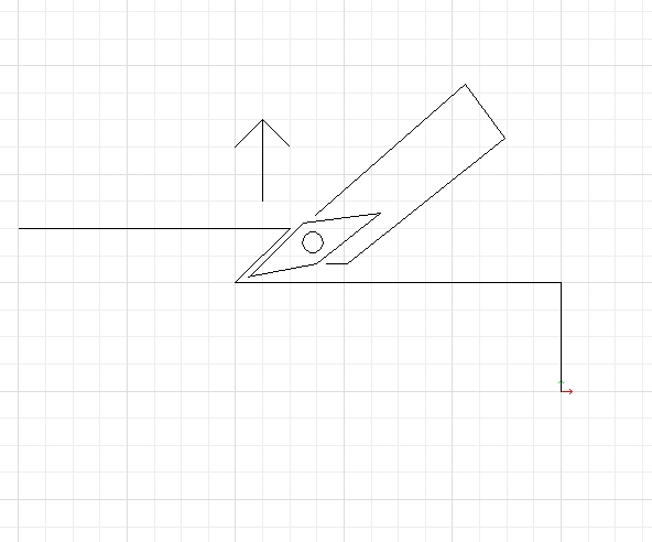
But, why does the path taper along the otherwise perpendicular faces ?
Doesn’t follow the contour very well.
Thanks
SC Turn .job (5.47 KB)
Sorry for the delay in replying. I just emailed you a temporary license.
The generated code should be in diameter mode.
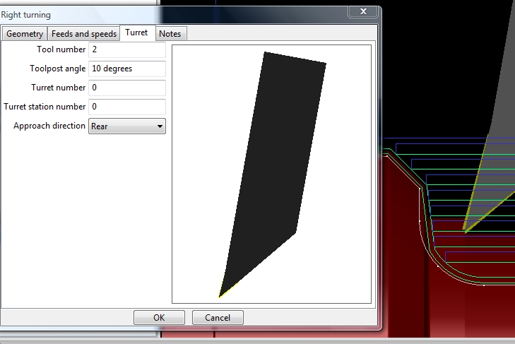
The slope had me puzzled for a moment but it is caused by your tool definition. You have a side angle of 0 degrees with a clearance angle of 2 degrees. When generating tool paths SheetCam adds the clearance angle to the side angle to ensure that you don’t end up dragging the whole length of the cutting edge against the work. You probably want to increase the side angle to around 5 degrees as most insert tools have a built in angle of at least 5 degrees.
G2/G3 are in the pipeline but it is likely to be quite some time before they are implemented.
That works well now, thank you for the (as always) concise explanation !
And thanks very much for the trial license.
Another question for you :
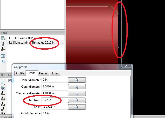
In the attached, a tool with a defined tip rad. of .015" will not attempt to cut the face of the stock unless the start point is entered as at least twice the
tip radius. Here I have .020" for cleanup but the tool refuses to go there.
If I make the start point Z +.032" it will work.
May be an easy fix ? On your end … or maybe mine.
Thanks again !
SC ex .job (4.73 KB)
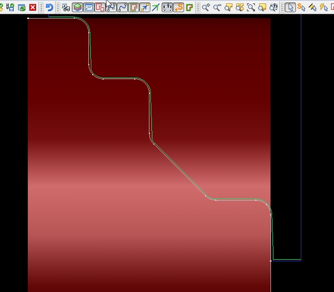
It’s starting the path 1 tool radius in from the start point and ending 1 tool radius before the end point.
Looking at the code I specifically offset the start and end points but now I have no idea why I did it!
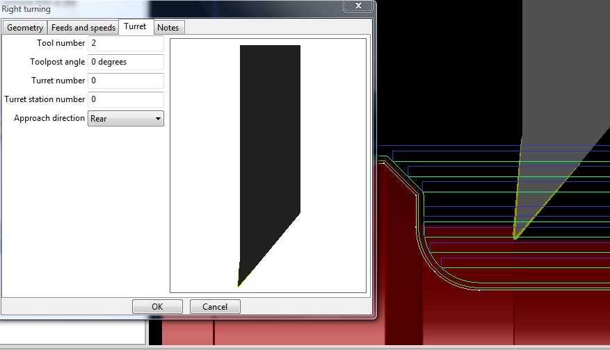
Changing the tool post angle in the Turret tab also has a strange effect on the toolpath.
It actually cuts closer to the profile than the (my) graphics show, but you can watch the Z DRO as it certainly does in fact cut a shallow taper to that face.
Changing the angle to a negative value shows a better toolpath but of course wrecks the shank and toolbit.
Looks like a +/- angle direction in the calcs might correct this ?
… meant to include the .job for the previous post.
Thought maybe Tip Tan or Tip Center would make a difference, didn’t seem to.
Thanks
SC Turret TP angle.job (4.74 KB)
Looks like the Start and End Points are only in reference to the Z axis, but needs to also include the X … Start 0.0 in this case ?
Similar to the way Dolphin does it ?
In Dolphin, one specifies an X and Z for the Start and End of the path.
Thanks,
![]()
OK, 1 more.
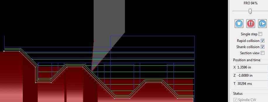
I’m getting ready to buy the lic and cut some actual parts. But can’t get past this collision detail.
Not sure how to get around it as I’ve configured the tool many ways to allow sufficient clearance … ( I think).
Looks like it might want to rapid to the clearance X through the relief angle of the bit … ? Not sure.
Rapid collision.job (5.91 KB)
It looks like the taper from the tool post angle is caused by the path generator appying the tool path angle the wrong way around. Reversing the turrent angle generates the correct tool paths but simulation will get upset. I’ll have to fix this.
The outer diameter and inner diameter are roughly the equivalent to Dolphin’s X start and end X coordinates. I must admit I plagiarised a bit from Fusion 360’s workflow. It’s a very long time since I last used Dolphin.
The rapid collision warning is a tricky one to fix. The tool paths are fine. If you zoom in on the collision area and simulate the cut at very low speed you can see it is fine. The problem is in the way simulation works. It works in discrete steps (roughly 30 steps/second). The amount the tool moves between steps increases as the feed rate increases. The bigger the steps the less accurate collision detection is. I need to do some work on this to make it less trigger happy.
It amazes me every day how a one man show is able to create such a robust piece of software like SheetCam. Kudos, Les.
Hi Les. looks like maybe the initial perpendicular retract should be at feed rate, then rapid. Or, more like the way the rapid retraction is done in the M3 wizards …G00 angled away from the shoulder.
Thanks !
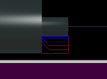
Attempting a G0 while the tool is currently “under” the material.
An exaggerated view …
Maybe G1 out the depth of the cut to clear the material, then G0.