Page 1 of 1
Kerf Width
Posted: Sat Jun 24, 2017 5:27 pm
by Mr. Fixit
Hi all,
Can someone tell me how to determine what kerf width I would need to include for a given plasma tool selection if i am creating my own set of tool tables? The cut tables that i have as provided by Thermal Dynamics does not include any info for kerf width. It has material type, material thickness, voltage, amperage, pierce height and cut stand off height, no kerf info. How can i get this information?
Thank you,
Steve
Posted: Sat Jun 24, 2017 9:15 pm
by WyoGreen
Steve,
You can run straight line test cuts on each of your tools, leaving the torch height control off. Make sure your cut height is correct, and pay attention to the cut voltage DRO. You can then verify that the cut voltage agrees with the set voltage, and measure the kerf width of the cut. You'll want to do this with new consumables, as that is the best cut that you will get.
Steve
Posted: Sat Jun 24, 2017 9:31 pm
by Mr. Fixit
WyoGreen wrote:Steve,
You can run straight line test cuts on each of your tools, leaving the torch height control off. Make sure your cut height is correct, and pay attention to the cut voltage DRO. You can then verify that the cut voltage agrees with the set voltage, and measure the kerf width of the cut. You'll want to do this with new consumables, as that is the best cut that you will get.
Steve
So If I am understanding correctly, I would create a tool for a given material spec based upon the manufacturers chart Thermal Dynamics) and not input any kerf width when I set up the tool. Then with THC off, I make a straight line cut while checking the DRO voltage with the correct height and then measure the kerf when done? Then edit the tool and put the kerf measurement into the specific tool. Am I close? Thank you.
Posted: Sun Jun 25, 2017 10:14 am
by Les Newell
I'd run with THC on but it shouldn't matter too much. Another way to measure the kerf is to cut a 2" or 3" square with no offset. Now measure the square. It will be undersize The amount of undersize is the kerf width. The advantage of this method is that it allows for variation in width through the thickness of the cut.
Posted: Sun Jun 25, 2017 10:59 am
by Mr. Fixit
Les Newell wrote:I'd run with THC on but it shouldn't matter too much. Another way to measure the kerf is to cut a 2" or 3" square with no offset. Now measure the square. It will be undersize The amount of undersize is the kerf width. The advantage of this method is that it allows for variation in width through the thickness of the cut.
Les,
With either method, do I leave the kerf box in the tool setting blank? If so, will Sheetcam know how post process for the test(s)
Thanks,
Steve
Posted: Sun Jun 25, 2017 11:43 am
by Les Newell
If you use 'no offset', SheetCam ignores the kerf width so it doesn't matter what you have in the box.
Posted: Sun Jun 25, 2017 11:46 am
by Mr. Fixit
Les Newell wrote:If you use 'no offset', SheetCam ignores the kerf width so it doesn't matter what you have in the box.
Great. Now I think I have some good options and a better understanding.
Thanks again.
Posted: Sun Jun 25, 2017 7:08 pm
by motoguy
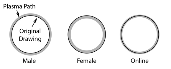
What tool offset (or kerf width compensation) does.
In the top photo, no offset puts the center of the tool (plasma arc, end mill, etc) directly on top of the part. This means the part will be slightly undersize, due to 1/2 of the tool (plasma arc, mill, etc) cutting INSIDE the part, and 1/2 cutting outside. When you use an offset, it scoots the tool over. so that the outside edge of the tool is along the outside edge of the part. This gives a final part of correct dimensions.
Inside offset is "female" in the bottom photo. Outside offset is "male" in bottom photo. No offset is "online" in bottom photo. The kerf width you enter in the tool chart determines how far off the centerline of the part the arc is centered. Ie, it determines how "thick" the gray line in the bottom photo is.

setting kerf width
Posted: Tue Oct 10, 2017 5:10 pm
by LensGenie
The way I did mine ( which is probably wrong since I'm self taught ) was to run "no" offset 6" test cuts then used a digital caliper to measure the the width of the cut near the center of the cut, then divide by 2.
But if I were you, I'd listen to Les and do it like he says